


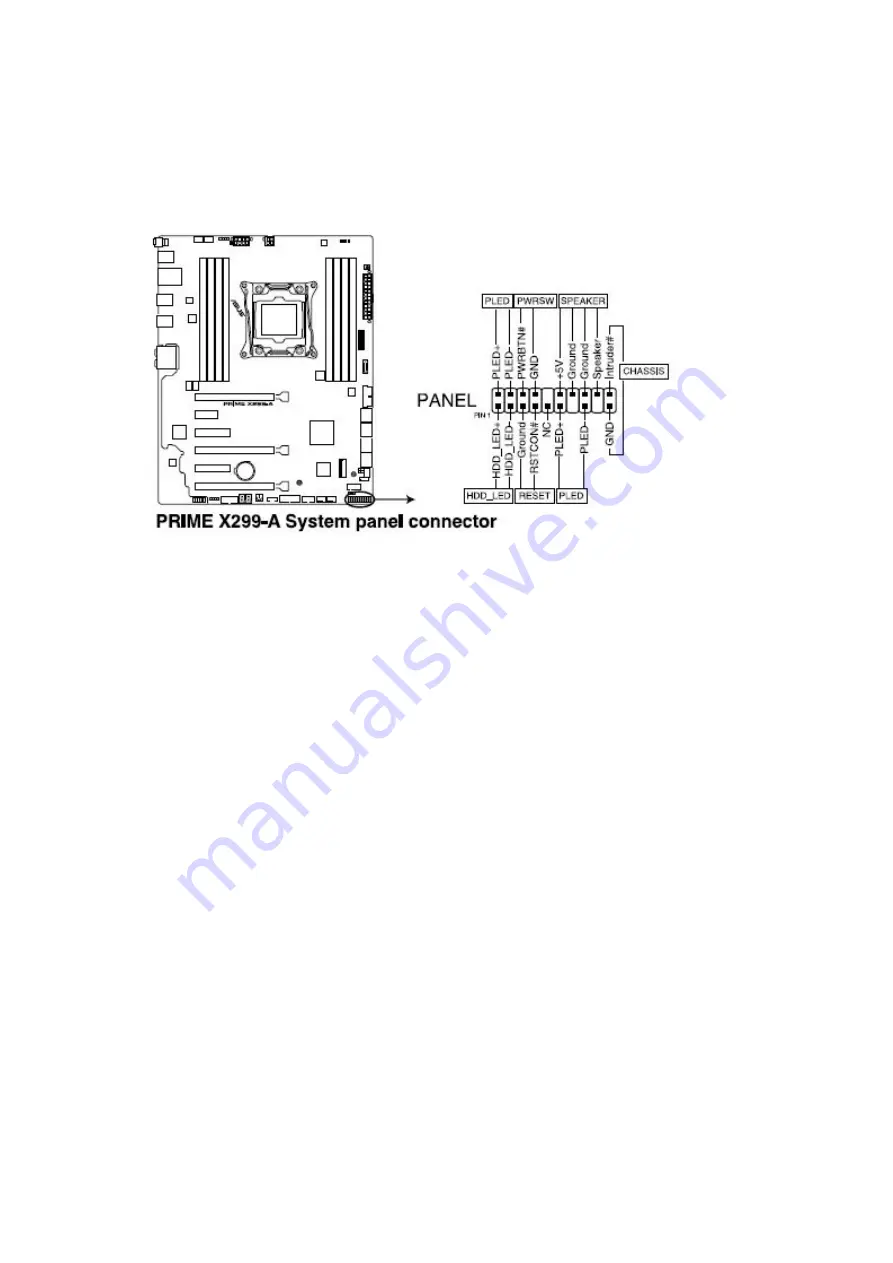
System panel connector (20-3 pin PANEL)
This connector supports several chassis-mounted functions.
•
System power LED (2-pin or 3-1 PLED)
This 2-pin or 3-pin connector is for the system power LED. Connect the chassis power LED cable to
this connector. The system power LED lights up when you turn on the system power, and blinks
when the system is in sleep mode.
•
Hard disk drive activity LED (2-pin HDD_LED)
This 2-pin connector is for the HDD Activity LED. Connect the HDD Activity LED cable to this
connector. The HDD LED lights up or flashes when data is read from or written to the HDD.
•
System warning speaker (4-pin SPEAKER)
This 4-pin connector is for the chassis-mounted system warning speaker. The speaker allows you to
hear system beeps and warnings.
•
ATX power button/soft-off button (2-pin PWRSW)
This connector is for the system power button. Pressing the power button turns the system on or
puts the system in sleep or soft-off mode depending on the operating system settings. Pressing the
power switch for more than four seconds while the system is ON turns the system OFF.
•
Reset button (2-pin RESET)
This 2-pin connector is for the chassis-mounted reset button for system reboot without turning off
the system power.
Chassis intrusion connector (2-1 pin CHASSIS)
x
This connector is for a chassis-mounted intrusion detection sensor or switch. Connect one end of
the chassis intrusion sensor or switch cable to this connector. The chassis intrusion sensor or switch
sends a high-level signal to this connector when a chassis component is removed or replaced. The
signal is then generated as a chassis intrusion event.
Содержание Spirit X299-AS
Страница 1: ...Spirit X299 AS User Guide Revision 2 0 August 2018...
Страница 10: ...Removing the Case Cover Unlatch the cover and open the case from the back 1 Slide the side cover back 2...
Страница 11: ...Lift the three tabs as illustrated and pull back the front bezel 3 That opens the front of the case 4...
Страница 18: ...Specifications Summary Asus Desktop Board Prime X299 A specifications summary...
Страница 19: ......
Страница 20: ......
Страница 21: ......
Страница 22: ......
Страница 23: ......
Страница 26: ...Asus Motherboard Components...
Страница 50: ...Q Code table...
Страница 51: ......
Страница 52: ......
Страница 56: ......
Страница 59: ...3 Situate mounting ring according to diagram 4 Place special screw extenders into mounting ring...
Страница 61: ...7 Twist reservoir counterclockwise 8 Screw reservoir mounting ring assembly onto motherboard...
Страница 62: ...9 Attach cable connector from reservoir to fan assembly 10 Attach hoses from reservoir...
Страница 65: ......
Страница 76: ...Slide the optical drive out of the assembly 4...


