background image


37  

S

ECTION

 8

vehicle movement. Assign units to the parallel 

movement in the same way as the main vehicle 

movement.
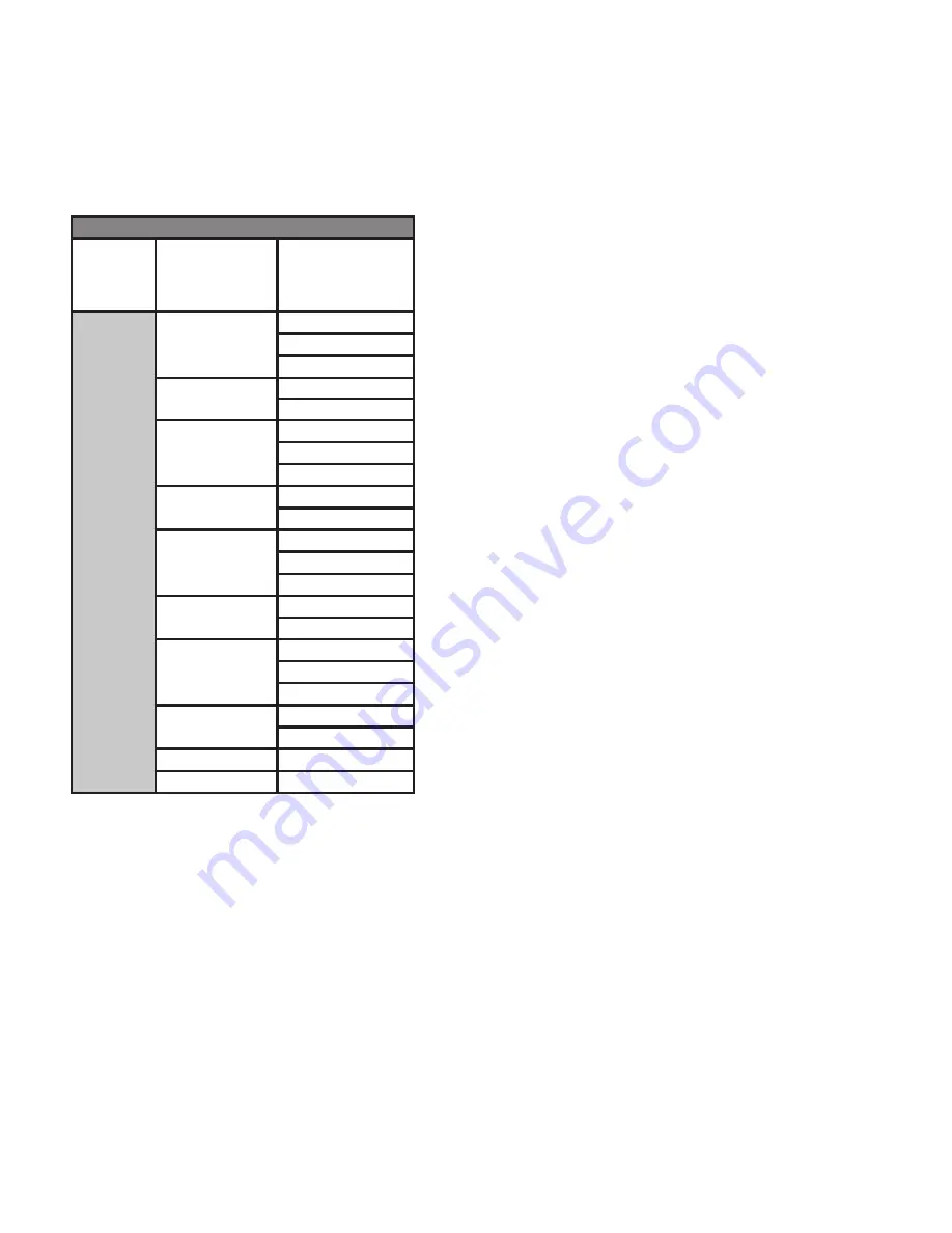
The Editing Phases chart below indicates the 

permissable parallel movement for every vehicle 

movement.

Edi

Ɵ

 ng Phases

APPLY MOVEMENT

APPLY PARALLEL 

MOVEMENT 

(permissible based on 

choice of B column)

DIRECTION

NORTH

SOUTH

NORTH WEST

PED NORTH SOUTH

NORTH WEST

NORTH

SOUTH EAST

SOUTH

NORTH

SOUTH EAST

PED NORTH SOUTH

SOUTH EAST

SOUTH

NORTH WEST

EAST

WEST

EAST NORTH

PED EAST WEST

EAST NORTH

EAST 

WEST SOUTH

WEST

EAST

WEST SOUTH

PED EAST WEST

WEST SOUTH

WEST

EAST NORTH

PED N/S

PED N/S

PED E/W

PED E/W

Once a phase has been edited press the BACK 

button to save changes and go back to the PHASE 

SETTINGS screen.

EDIT PHASE TIMING

Each phase has a column of editable parameters.
To edit, use the arrow buttons to move the cursor 

to the desired parameter. Press ENTER to edit 

the selection and use the UP and DOWN arrows 

to cycle through available options or increase/

decrease timing parameters. Press the BACK or 

ENTER button to lock a parameter in memory.
The following parameters can be edited seperately 

for each phase (column). 

Note: There are two 

pages of options and parameters. Use the UP and 

DOWN arrow buttons to navigate to both pages.

• 

MIN GREEN -

 The minimum time in seconds 

a phase will remain green. Used only when 

actuation is enabled.

• 

MAX GREEN - 

The maximum time in seconds a 

phase will remain GREEN until it returns to RED.

• 

YELLOW - 

The YELLOW time in seconds 

between the transition from GREEN to RED.

• 

RED - 

The time in seconds phase will be RED 

before serving the next phase.

• 

PASSAGE (Gap, Extension) - 

The amount of 

time in seconds added to the green interval for 

every vehicle detection that occurs. It begins 

counting down when the vehicle detection 

(actuation) is removed.

• 

CALL - 

Parameters that pertain to the use of 

actuation. Each available option is de

fi

 ned 

below.

  MIN (Minimum Recall) 

- the parameter 

causes the controller to place a call for 

vehicle service on the phase. The phase 

is timed at least for its minimum green, 

regardless of whether there is a vehicle 

detection event on the movement.

  MAX (Maximum Recall)

 - the parameter 

causes the controller to place a continuous 

call for vehicle service on the phase, which 

results in displaying the green indication for 

its maximum duration every cycle.

  RRED (Rest Red) 

- When actuation is set 

to “rest red” the signal will remain red until 

an approaching vehicle is detected. The 

fi

 rst 

approaching vehicle detected will send a 

command to the controller and that phase 

will become active. If an approaching vehicle 

is detected by another traf

fi

 c sensor, that 

phase will be put in queue until the active 

phase is complete. Once all phases are 

complete and no further phases are in queue, 

all phases will remain red until a vehicle is 

detected.

  RGRN (Rest Green)

 - When actuation is set 

to “rest green” it will remain green following 

actuation and expiry of the green time, while 

the other phase will remain red until a vehicle 

is detected. If an approaching vehicle is then 

detected by another traf

fi

 c sensor, that phase 

will be put in queue until the active phase 

has reached the minimum green time and 

no vehicles are in queue or has reached the 

maximum green time, regardless of vehicles 

being in queue. The phase with the vehicle 

in queue will become active and will remain 

green until a vehicle is detected by a traf

fi

 c 

Содержание PTL 2.4 Series

Страница 1: ...PTL 2 4x Portable Traffic Signal Manual REV 07 02 10 22 THE LEADER IN TRAFFIC CONTROL SYSTEMS TM ...

Страница 2: ...oduced without any kind of warranty Improvement and changes in this manual due to typographical errors inaccuracies in current information or improvements to programs and or equipment may be made at any time without notice The user is responsible for verifying use of the latest version by contacting North America Traffic REPORTING ERRORS AND RECOMMENDING IMPROVEMENTS You can help improve this manu...

Страница 3: ...22 6 3 O 23 6 4 S O 25 6 5 H 25 7 S U W Z 27 7 1 L B M 28 8 A M 34 8 1 N 34 8 2 NEMA D 35 8 3 E P 36 8 4 T D D W O 38 8 5 O A M 39 8 6 E S 40 9 C M 42 9 1 S C M G 3 43 9 2 O W G 1 44 9 3 O G 2 45 10 D M 46 10 1 F D L 46 10 2 S S D 47 10 3 S I E 47 11 O E 48 11 1 R R 48 11 2 V D 50 11 3 R M S RMS 50 11 4 E V P 51 11 5 I I 51 11 6 D A 52 12 C 53 12 1 R S 53 12 2 H 53 13 P S I 54 13 1 S 54 13 2 B 54 ...

Страница 4: ...he jacks are fully retracted and locked into place The controller cabinet door has been shut and secured The hitch safety chains are secured The connection for the trailer lights has been secured and tested check right left turn signals hazard lights and brake lights for correct function Drive ahead about 10 feet and do a final walk around to ensure that all lock down points are secure safety chai...

Страница 5: ...Fire Batteries release an explosive hydrogen gas while being charged Keep cigarettes sparks flames and any other ignition sources away at all times Acid Burns Battery acid can cause burns if it comes in contact with exposed skin and can cause blindness when in contact with your eye s Always wear protective goggles and gloves when working with batteries Electrical Burns An electrical short between ...

Страница 6: ...once the preceding phase is complete Turn Phases Protected assigns the right of way to drivers turning left and allows turns to be made only on a green arrow display Permissive operation requires left turning drivers to yield to oncoming or conflicting ve hicle and pedestrian traffic before completing the turn A permissive left turn is served con currently with the adjacent through movement Protec...

Страница 7: ...Flashing Phase status is GREEN Solid Phase status is AMBER or RED 2 Horizontal Mast Arm The galvanized painted steel telespar arm that contains the signal head s that are positioned over the roadway when fully deployed 3 Communication Link Radio Transceiver A Radio Transceiver is installed in each PTL 2 4x Unit in order for the units to communicate The Radio Transceiver is a 1 Watt system designed...

Страница 8: ...cle batteries in series parallel to generate 24 VDC Batteries are charged using the 40 Amp smart charger external plug provided near cabinet door providing easy access for connection to a 120 VAC source Batteries receive some assisted energy supplied by the solar array for more information see item 6 Solar Array above Note For more detailed information pertaining to batteries charger and solar arr...

Страница 9: ...hes main power on off and lift system control switches 6 Battery Charger used to charge the batteries when unit is plugged into a 120 VAC power source 7 Solar Controller Regulator stabilizes and transmits the energy collected by the solar panel to the battery bank 8 Fuse Block fuses for all electrical functions 9 Isolated Power Distribution Studs the distribution point to which power from the batt...

Страница 10: ...locking pin c Place base of screw jack on the ground d Line up the nearest holes on the screw jack and put the locking pin through e Secure locking pin with cotter pin f Turn crank until screw jack is firmly on the ground g Repeat for each screw jack h Once completed do a walk around and check to make sure none have lifted off the ground and that the trailer is level 3 Disconnect PTL 2 4x tongue f...

Страница 11: ...les on mast arm support e Put locking pin in hole f Put cotter pin in locking pin 7 Unlock the mast arm support from the signal post and move into position a Remove cotter pin b Remove locking pin c Swing mast arm support towards the rear of the signal d Continue swinging the mast arm until it stops at the signal post 8 Raise the main light post Note Ensure there is no overhead wires or obstructio...

Страница 12: ...osition use the HORIZONTAL ARM toggle switch to extend the 17 foot signal housing over the roadway by an additional 44 inches 9 Position the solar panels a Using a 9 16 wrench loosen the nuts found on each side of the solar panel support b Tilt the solar panels to a 45 angle 0 15 30 45 60 5 10 20 25 35 40 50 55 c Tighten the nuts on both sides of the solar panel support to secure the panels at a 4...

Страница 13: ...iler c Using a 9 16 wrench loosen the nuts found on each side of the solar panel support d Tilt the solar panels until it is at 0 horizontal e Tighten the nuts on both sides of the solar panel support to secure the panels at a 0 angle 0 15 3 0 45 60 5 10 20 25 35 40 50 55 2 Lower the signal post a Unlock the pad lock and open the signal post lock bar b Open the control cabinet Using the HORIZONTAL...

Страница 14: ...tion a Remove the cotter pin from the locking pin b Remove the locking pin c Swing mast arm toward the mast arm support d Push up on the mast arm to place in between the supports e Put locking pin in holes f Put cotter pin in locking pin 5 Place tongue on machine a Position tongue in front of machine b Firmly slide tongue into trailer until the front and rear holes are lined up c Insert the two lo...

Страница 15: ...ball hitch coupler b Crank the screw jack until the base is off the ground c Remove cotter pin d While holding the base of the screw jack remove locking pin e Raise the base until the bottom hole is lined up with the main locking hole f Put the locking pin in the screw jack locking hole g Put the cotter pin in the locking pin h Repeat for all screw jacks ...

Страница 16: ...ctuator motor housing using a 3 16 Allen wrench Using the 1 4 drive extension at least 8 in length lower the main light post until it reaches the holding bracket to prevent stripping set the drill to a low clutch setting If required repeat the process for the horizontal mast arm to retract the light housing extension PROGRESSIVE AUTOMATION ACTUATOR Tools Required T 30 Torx bit 6mm hex bit with an ...

Страница 17: ...bs 1334 kg Ensure all lifting and rigging equipment is rated to lift the load Failure to follow this instruction can result in damage to the trailer and associated equipment 1 Open mast arm assembly to horizontal position see Fig 2 3 Note Do not lift trailer with the light post in the vertical position 2 Tilt the solar array to 60 see Fig 2 3 3 Connect straps as per trailer signal housing configur...

Страница 18: ...f the machine 3 Remove the bolt shown from the signal housing bracket Loosen the other bolt if needed 4 Pivot the signal head 180 and replace the bolt back into the corresponding hole 5 For the lower signal head on the main light post repeat steps 3 4 High High 1 Repeat steps 1 4 from the High Low instruction for the outside signal head 2 For the other signal head located on the mast arm remove bo...

Страница 19: ...ER Button used to confirm a selected value or open a parameter for editing 5 Directional Buttons allows the user to toggle through menus various screens and cycling through parameters open for editing 6 USB Port used to import export software files traffic control plans and fault data logs 7 J Plugs J1 J2 I O connections to the terminal block by means of wire harnesses 8 Serial Port J0 connection ...

Страница 20: ...asscode From factory this passcode is 0 8 0 0 Once this is entered a prompt will appear to enter a new passcode If your custom passcode is ever forgotten call North America Traffic 1 877 352 4626 After a new passcode is set in order to alter any settings the software will need to be unlocked This can be accomplished either by unlocking the software via the OPTIONS menu or by selecting any option t...

Страница 21: ... a soft button is selected i e Secondary 1 GREEN Use the or directional buttons to increase or decrease the highlighted integer Use the and directional buttons to toggle between MAX and MIN times Lock parameters in memory by pressing ENTER ENTER pressing any other soft button or by shifting the selection to the opposing timing input MAX MIN Toggling Through the Unit Diagnostic Tab OPTIONS HELP PRI...

Страница 22: ...for the signal When actuation is enabled green max is the maximum amount of time the signal will stay green when continuous detector activations occur If the green max time is reached the signal transitions to the yellow time followed by the red time and then the next phase will turn green If actuation is disabled green max is used as the standard green time Green Min Min only appears when Actuati...

Страница 23: ...vehicle actuations that occur during the yellow and red display of the signal phase When the controller determines if the phase should be called for service it uses the remembered actuations to call the phase to service even if the detected vehicle has since left Non Lock The controller does not remember actuations and the phase will be called to service only if it has a currently occupied detecto...

Страница 24: ...e cleared once it has been resolved Export All Logs fault logs and data logs can be exported via USB as a csv file Default Behavior allows the user to set the signal default mode that will be displayed in the event of a fault displayed across network Note Each Secondary unit can be modified independently to that of the Primary unit However a change to the SITE LAYOUT or to the PRIMARY DEFAULT sett...

Страница 25: ...EL OF OPERATION GATE ARM INTRUSION ALARM PREV PAGE LOCK SOFTWARE GEN 3 BASIC FEET NEXT PAGE Compatibility With allows the Gen 3 system to operate with older Gen 1 or 2 controllers If compatibility with an older Gen controller is selected some programming options within the Gen 3 software will be inaccessible grayed out in order to comply with the older versions see SECTION 9 COMPATIBILTY MODE Note...

Страница 26: ...e language settings Note these instructions will assist with changing the operating system language from Spanish ESP to English ENG OPERATOR SHALL BE FULLY TRAINED OPERATOR SHALL BE OPTIONS FEB 01 17 09 53AM PROGRAM MODEL V HOME BATTERY 24 0 VOLTS UNIT PRIMARY RADIO CHANNEL 03 RADIO SIGNAL DEFAULT FLASH RED PRESS START TO RESUME LIGHT POSTS WORK ZONE SETUP HELP START FLASH YELLOW FLASH RED PRI SEC...

Страница 27: ...e selection to ENGLISH press the ENTER button Power off the system and wait 15 seconds for the controller to fully power down LED lights on faceplate go dark Note this step is required to implement the language settings change Failure to do so will leave the language set to ESPAÑOL Turn the power back on and operate the system as required ...

Страница 28: ...ss the BACK button to return to the HOME screen 6 Repeat steps 3 to 5 for each secondary unit 7 Proceed to primary unit to continue setup Primary Setup 1 Proceed to Primary unit a Select WORK ZONE SETUP b Set the UNIT ID to Primary c Choose the RADIO CHANNEL that was chosen on the secondary units d Select the LAYOUT based on your work zone Refer to SECTION 7 1 LAYOUTS BASIC MODE for a detailed lis...

Страница 29: ...Secondary 1 2 3 Auto One Way 1 Cross 1 Side Primary Secondary 1 2 3 4 Auto One Way 1 Cross 2 Side Primary Secondary 1 2 3 4 5 Auto One Way 2 Cross Roads Primary Secondary 1 2 3 4 5 Auto One Way 2 Cross 1 Side Primary Secondary 1 2 3 4 5 6 Auto One Way 2 Cross 2 Side Primary Secondary 1 2 3 4 5 6 7 Auto Two Way Zone Manual Mode Primary Secondary 1 Manual Two Way 1 Side Primary Secondary 1 2 Auto Tw...

Страница 30: ...ONE MIN only active when ACTUATION is enabled Default Behaviour Settings can be applied to all units in the network or customized per unit Note each additional side road requires another secondary unit SECONDARY 1 2 WORK ZONE SETUP SETTINGS UNIT ID SECONDARY 1 2 RADIO CHANNEL 0 9 HARDWIRED PRIMARY OPTIONS SETTINGS CONTROL MODE Choose AUTO DEFAULT BEHAVIOUR Choose FLASH RED SOLID SETTINGS RED or FL...

Страница 31: ... MIN 1 300 MAX 1 300 MIN only active when ACTUATION is enabled Default Behaviour Settings can be applied to all units in the network or customized per unit Note each additional cross road requires two secondary units SECONDARY 1 5 WORK ZONE SETUP SETTINGS UNIT ID SECONDARY 1 5 RADIO CHANNEL 0 9 HARDWIRED PRIMARY OPTIONS SETTINGS CONTROL MODE Choose AUTO DEFAULT BEHAVIOUR Choose FLASH RED SOLID SET...

Страница 32: ... ACTUATION is enabled Default Behaviour Settings can be applied to all units in the network or customized per unit Note each additional side road requires another secondary unit SECONDARY 1 2 WORK ZONE SETUP SETTINGS UNIT ID SECONDARY 1 2 RADIO CHANNEL 0 9 HARDWIRED PRIMARY OPTIONS SETTINGS CONTROL MODE Choose AUTO DEFAULT BEHAVIOUR Choose FLASH RED SOLID SETTINGS RED or FLASH YELLOW LEVEL OF OPER...

Страница 33: ...aviour Settings can be applied to all units in the network or customized per unit TWO WAY 1 CROSS ROAD Work Zone PRIMARY SECONDARY 1 PILOT CAR HHR SECONDARY 1 WORK ZONE SETUP SETTINGS UNIT ID SECONDARY 1 RADIO CHANNEL 0 9 HARDWIRED PRIMARY OPTIONS SETTINGS CONTROL MODE Choose PILOT CAR MODE SYNC RADIO REMOTE Follow screen instuctions DEFAULT BEHAVIOUR Choose FLASH RED SOLID SETTINGS RED or FLASH Y...

Страница 34: ... ACTUATION is enabled SINGLE UNIT AUTO eg Highway ramp metering Work Zone PRIMARY HHR STOP PRIMARY OPTIONS SETTINGS CONTROL MODE Choose SINGLE UNIT MANUAL SYNC RADIO REMOTE Follow screen instructions DEFAULT BEHAVIOUR Choose FLASH RED SOLID SETTINGS RED or FLASH YELLOW LEVEL OF OPERATION BASIC WORK ZONE SETUP SETTINGS UNIT ID PRIMARY RADIO CHANNEL 0 9 LAYOUT SINGLE UNIT Default TIMING see 6 1 CHAN...

Страница 35: ...raffic setup PLAN 5 MON FRI SAT SUN 6 00AM 12 00PM 1 00PM 7 30AM 3 00PM 9 30AM 6 00PM 9 00PM 1 2 3 4 5 6 7 8 PHASES 1 2 3 4 5 6 7 8 7 15 3 2 4 VIEW EDIT PLAN NUMBER 1 MIN GREEN PASSAGE YELLOW RED MAX GREEN FEB 01 17 09 53AM HOME WZ SETUP PHASE SETTINGS ACTIVE PLAN NUMBER 4 1 4a 3 4b 5 6 8 9 7 2 2a 2b 1 Systems Tray 2 NEMA Phase Diagram see section 8 2 a Ring One b Ring Two 3 Isolated Phase Within ...

Страница 36: ...IER The selection box can be moved up to the TIME OF DAY tabs to edit DAYS OF THE WEEK and START TIME More phase settings options can be found by moving the selection cursor down in the phase settings chart Plans will automatically be saved when exiting the Phase Settings screen or moving from one plan to another 8 2 NEMA D A NEMA Phase Diagram is an industry standard for traffic control diagrams ...

Страница 37: ...te Sensor 32 pairs with Head A Sensor 33 pairs with Head B Note If both heads A and B are to be assigned to the same phase ie a turn movment ensure both are activated in ASSIGN UNITS for that phase TURN PHASES Note Wiring and hardware changes may be required to setup custom turn movements Contact North America Traffic for further detail ASSIGN BARRIER Barriers provide a synchronization point betwe...

Страница 38: ...t phase PASSAGE Gap Extension The amount of time in seconds added to the green interval for every vehicle detection that occurs It begins counting down when the vehicle detection actuation is removed CALL Parameters that pertain to the use of actuation Each available option is defined below MIN Minimum Recall the parameter causes the controller to place a call for vehicle service on the phase The ...

Страница 39: ... the phase Select CLEAR SETTINGS A prompt will appear to proceed with clearing all the data press ENTER on the controller To exit without clearing the settings press BACK Clearing the settings will only erase settings associated to that phase It will not affect any existing time of day settings EDITING PHASE 1 APPLY MOVEMENT ASSIGN BARRIER ASSIGN UNIT S ASSIGN UNIT S APPLY PARALLEL MOVEMENT FEB 01...

Страница 40: ... Press BACK or ENTER to save and close Notice a tab appears with the selected start time Create additional start times as required Note that two start times are required to have any affect It is now possible to edit individual phase parameters MAX GREEN RED etc per selected time of day Use the directional buttons to move the cursor to the desired day s of week tab and appropriate start time tab an...

Страница 41: ...OF THE WEEK tab for both the weekend SAT SUN and weekdays MON FRI SECONDARY 3 SECONDARY 1 PRIMARY SECONDARY 2 N S through the plans Locate the required plan To edit or change a plan refer to sections 8 3 and 8 4 On the opposite side of the screen cycle through the ACTIVE PLAN NUMBER to select the plan to be operated Navigate back to the home screen When all required Secondary Units are connected p...

Страница 42: ...signed to each day or grouping of days Note For actuated phases 3 and 7 input both MIN and MAX GREEN times input PASSAGE time Select a CALL parameter typically RRED rest red Select a LOCKING type typically YEL yellow lock When the steps have been followed correctly the programmed NEMA Diagram should appear like the diagram below 1 2 3 4 5 6 7 8 PRI B A B PRI A SEC2 A B SEC3 A B SEC1 A SEC1 B ...

Страница 43: ...e Differences and limitations of compatibility mode are outlined below ALL STOP Gen 1 Portable Traffic Signal Controller SEC MENU START ENTER AMBER TIME SEC PH 2 3 RED SEC PH 2 3 GREEN SEC DISTANCE PH1 RED SEC PH1 GREEN SEC TIME CONTROL FULL SENSOR BACK LIGHT DISABLE FLASH RED POWER ON CHARGE OPTION ALERT IN QUEUE RECEIVE TRANSMIT STATUS RED AMBER GREEN LIGHTS MASTER SEC MASTER VOLTS SECONDARY VOL...

Страница 44: ...ect WORK ZONE SETUP 3 Set the UNIT ID to PRIMARY 4 Set the RADIO CHANNEL to the same as all other secondary units in the network 5 From the home screen select OPTIONS and scroll down until COMPATIBILITY is visible 6 Set COMPATIBILITY to the required mode of compatibility either GEN 1 or GEN 2 7 Ensure LEVEL OF OPERATION is set to BASIC 8 Refer to SECTION 7 SETTING UP A WORK ZONE for detailed infor...

Страница 45: ...ed phase i e 1 phase 1 2 phase 2 SITE LAYOUT Pri S1B S2A S2B S3A S3B ONE WAY ZONE 1 2 ONE WAY 1 SIDE 1 2 3 ONE WAY 2 SIDE 1 2 3 4 ONE WAY 3 SIDE 1 ONE WAY 4 SIDE 1 ONE WAY 5 SIDE 1 ONE WAY 6 SIDE 1 ONE WAY 1 CROSS ROAD 1 2 3 3 ONE WAY 1 CROSS 1 SIDE 1 2 3 3 4 ONE WAY 1 CROSS 2 SIDE 1 ONE WAY 2 CROSS ROADS 1 2 3 3 4 4 ONE WAY 2 CROSS 1 SIDE 1 ONE WAY 2 CROSS 2 SIDE 1 TWO WAY ZONE MANUAL MODE 1 1 TW...

Страница 46: ... S2 S3 S4 S5 S6 S7 ONE WAY ZONE 1 2 ONE WAY 1 SIDE 1 2 3 ONE WAY 2 SIDE 1 2 3 4 ONE WAY 3 SIDE 1 2 3 4 5 ONE WAY 4 SIDE 1 2 3 4 5 6 ONE WAY 5 SIDE 1 2 3 4 5 6 7 ONE WAY 6 SIDE 1 2 3 4 5 6 7 8 ONE WAY 1 CROSS ROAD 1 2 3 3 ONE WAY 1 CROSS 1 SIDE 1 2 3 3 4 ONE WAY 1 CROSS 2 SIDE 1 2 3 3 4 5 ONE WAY 2 CROSS ROADS 1 2 3 3 4 4 ONE WAY 2 CROSS 1 SIDE 1 2 3 3 4 4 5 ONE WAY 2 CROSS 2 SIDE 1 2 3 3 4 4 5 6 T...

Страница 47: ...disappears Note The exported file type is a csv named NATLogs and can be viewed in any spreadsheet software FEB 01 17 09 53AM PROGRAM MODEL V HOME OPTIONS 1 FAULT LOGS BATTERY 24 0 VOLTS UNIT PRIMARY RADIO CHANNEL 03 RADIO SIGNAL DEFAULT FLASH RED PRESS START TO RESUME EXPORT FAULT LOGS NEXT PAGE FAULT LOGS LINE DATE EVENT 0 1 3 2 4 JAN 13 17 8 50AM JAN 13 17 8 47AM JAN 12 17 12 18PM JAN 12 17 12 ...

Страница 48: ...rent phase TIME indicates how many seconds are remaining for the corresponding signal indication NEXT PHASE indicates which unit will be served by the following phase PHASES IN QUEUE displays which units will be served following the unit listed in NEXT PHASE 10 3 S I E Software updates and preprogrammed traffic plans can be imported via USB flash drive Exporting can be used to save plans or for tr...

Страница 49: ...essing the Red button initiates an ALL STOP command Pressing the Green button resumes system operation after an ALL STOP condition at the Primary signal Pressing the Black button resumes system operation after an ALL STOP condition at the Secondary signal Radio Remote Push Buttons Functions Manual Mode Pressing the Red button initiates ALL STOP Pressing the Green button will turn the Primary signa...

Страница 50: ...S NEXT PAGE AUTOMATIC LOCK SOFTWARE SYNC RADIO REMOTE 1 Press and hold the RED and BLACK buttons on the radio remote 2 Wait for prompt before releasing both buttons 1 4 Watt Radio WHITE WHITE 1 Watt REV 1 Radio BLACK WHITE 1 Watt Radio BLACK BLUE GREEN RED SIGNAL ACCEPTED PRESS AND HOLD BUTTON FOR 3 SECONDS TO SEND BEEP INDICATES LOW BATTERY KEEP REMOTE DRY MODEL NUMBER 500 1168 GREEN RED SIGNAL A...

Страница 51: ...esence information is transmitted to the traffic controller via detection outputs so that the timing can be adjusted dynamically Therefore vehicle waiting time is reduced and traffic flows are optimized There are up to eight 8 direction sensitive vehicle presence detection zones Video Camera Hardware Specifications Version Focal Distance Angle of View DetecƟon Area VerƟcal Horizontal Corner to Cor...

Страница 52: ...hich the detection event occurs Any conflicting phases displaying green are immediately terminated After which the corresponding red clearance interval is served and the approaching emergency vehicle is given a green indication This green indication is held as long as the EVP detection is present Once the EVP detection is no longer present traffic control resumes as programmed Both forms of EVP de...

Страница 53: ...n long distance work zones and or work zones varying in elevation i e Pilot Car work zones This antenna has an operational range up to 7 miles 11 3 km with line of site The directional antenna can easily replace the standard omni directional whip antenna and vice versa ...

Страница 54: ...uctural steel Close proximity to radio stations airports and power lines Dip Switch Settings 1 Watt Radio Module 1 6 5 4 3 2 O N 12 2 H Where it is required Weak RSSI signal strength Less than 50 consistently see Systems Tray No line of sight i e inside a parking garage tunnels across large steel bridges under an overpass Cable Requirements Minimum Cable Specification Single twisted pair with a gr...

Страница 55: ...ar array be inspected on a daily basis to ensure it is free of dirt and debris Should the array require cleaning use water and a mild soap and wipe clean Do not use harsh chemicals shovels rakes or any other metal tool to clean debris from the solar array as damage to the glass may occur Use a car snow brush or broom to remove snow or other large debris 13 2 B The PTL 2 4x battery bank is comprise...

Страница 56: ... message CHARGE FOR 24 to 48 HOURS on the screen Inactivity Lead acid batteries that are not in use will slowly discharge over time possibly leading to over discharge and damage to the batteries If the batteries will be inactive for a long period of time EXAMPLE sitting over the winter months then the charger should be plugged in periodically or ensure the solar panels have good exposure to the su...

Страница 57: ...ery charger is the correct gauge in good working condition and properly grounded 13 4 G U A minimum 1200 Watt generator is required to meet the power requirements of the battery charger Connection and Operation CAUTION Never start up the generator while connected to the battery charger This may lead to damage and or failure of the battery charger Generators can output high voltage spikes upon init...

Страница 58: ...tire was manufactured the 46th week of 2017 Proper Torque of Lug Nuts Ensure the lug nuts are torqued on a monthly basis Use a torque wrench The wheel lug nuts should be torqued to 120 ft lbs Note The lug nuts are torqued to spec at the factory Check and re torque after the first 10 miles 16 km 25 miles 40 km and again at 50 miles 80 km of travel This should also be done after every wheel removal ...

Страница 59: ...nut as required Please contact North America Traffic for Instructions c Inspect All Locking Pins for Excessive Wear or Damage d Inspect the Tongue Draw Bar for Any Signs of Damage e Test the Running Lights for Proper Function Inspect the electrical contacts in all plugs and re ceptacles for signs of wear or corrosion Replace and components as required f Safety Chain Inspection Inspect safety chain...

Страница 60: ...ary x to match Primary A ach radio cable to radio to radio transmi or Set the dip switches as per diagram see Sec on 12 1 Replace antenna Replace radio cable TURN ON PRIMARY UNIT Secondary wai ng for commu nica ons to start a er power is turned on Primary is not turned on Primary is on radio channel is different than Secondary x Primary is on radio cable is not a ached to transmi or Primary is on r...

Страница 61: ...nged to the same channel PROBLEM DETECTED ON LAMP X REPAIR MACHINE Current overload short circuit or underload open circuit lamp outputs Faulty wire connec on Faulty wires Faulty lamp Faulty controller Check connec ons and recon nect wiring Check wires replace where necessary Replace faulty lamp Replace faulty controller MALFUNCTION RESPONSE REPAIR MACHINE Undiagnosed MMU fault Call 877 352 4626 C...

Страница 62: ...read ing low Ba ery charge is below 23 6V machine will s ll operate Plug internal charger into 110V power source for min imum 24hrs of con nuous charging MALFUNCTION RESPONSE BATTERY DEAD CHARGE FOR 48 HRS MMU detected that the bat tery is too low to operate Ba ery charge is below 23 0V machine will not operate Plug internal charger into 110V power source for min imum 48hrs of con nuous charging M...

Страница 63: ... terminal Check and replace faulty wiring Check wiring diagram and terminal block DEFAULT ALL RED PRESS START TO RESUME Default solid red as shown on Primary machine Previous fault has cleared automa cally Press START bu on on Primary when ready to start program DEFAULT ALL RED Default solid red as shown on Secondary machine Previous fault has cleared automa cally Press START bu on on Primary when...

Страница 64: ...0150 1 Watt Radio Transceiver 500 0092 10 375 Antenna Coupler Cable 400 0209 24 Antenna Coupler Cable 400 0152 7dB Whip Antenna 500 0003 Antenna Base Plane Station 400 0146 PolyCase Radio Enclosure 400 0201 PolyCase Plate Kit 400 0202 12 Red LED Lamp 500 0691 12 Yellow LED Lamp 500 0692 12 Green LED Lamp 500 0693 12 Ball Cap Visor Yellow Black MISC 4 Back Lamp 24V 500 0737 4 Back Lamp grommet 500 ...

Отзывы: