


Carrier Remote IPE column installation
97
The NT7R59AA Carrier Panel assembly contains two 8-pin modular
jacks and the NT7R60AA Carrier/Alarm Panel assembly contains one
8-pin modular jack, which are used to connect carrier links.
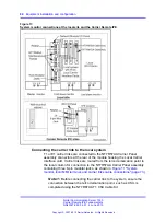
"Backplane to I/O panel connections on the IPE module" (page 94)
shows
the carrier connectors and the carrier link cable routing.
Note 1:
Before connecting the carrier link to the system, the connection
between the telco demarcation point such as CSU, should be completed
using the NT7R87AA T1 CSU Cable Kit.
Note 2:
To connect an E1 carrier terminated with BNC connectors, use
the NT7R67EA Coaxial Interface Adapter Cable to connect the 8-pin
modular jacks at the I/O panel to the BNC connector on each E1 carrier
link coming from the telco demarcation point. Also refer to
"Local Carrier Interface card DIP-switch positions and function" (page
67)
and
Figure 14 "Remote Carrier Interface card DIP-switch locations
to set SW1, SW2, SW5, and SW8 for E1
operation and carrier impedance of 75 Ohm.
To connect carrier links to the IPE module’s NT7R59AA Carrier Panel
and NT7R60AA Carrier/Alarm Panel assemblies at the remote site, follow
the steps in
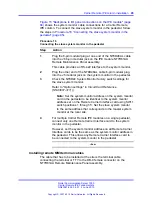
Procedure 18 “Connecting the carrier link to the Remote IPE
Procedure 18
Connecting the carrier link to the Remote IPE module
Step
Action
1
Route all three carrier links to the rear of the Carrier Remote IPE
column housing the Remote Carrier Interface card.
2
Identify carrier 0 (primary), carrier 1 (primary), and carrier 2
(primary or spare) and the corresponding connectors on the
NT7R59AA Carrier Panel and the NT7R60AA Carrier/Alarm
Panel assemblies.
Note: Compare carrier circuit ID numbers of carrier links at
the local site (that were recorded during the installation of the
carrier links at the local site) with the carrier circuit ID numbers
of the carrier links at the remote site. Make sure they match
so that the circuit ID of carrier 0 at the local site matches with
circuit ID of carrier 0 at the remote site. Repeat this matching
for carrier 1 and carrier 2. This eliminates cross-connection
of carrier links, which causes transmission problems. Refer
to
“Verifying carrier link connections at the remote site” (page
3
Plug each carrier cable 8-pin modular plug into the
corresponding 8-pin modular jack on the NT7R59AA Carrier
Nortel Communication Server 1000
Carrier Remote IPE Fundamentals
NN43021-555 04.01
4 June 2010
Copyright © 2007-2010 Nortel Networks. All Rights Reserved.
.
Содержание Communication Server 100
Страница 213: ......


