Local equipment installation
73
For multiple Local Carrier Interface cards, refer to
"Daisy-chaining multiple Local Carrier Interface cards" (page 80)
and
Figure 27 "Multiple LCIs connection diagram (local site daisy-chain
connection)" (page 199)
that shows how to connect multiple Local Carrier
Interface cards to multiple I/O panel assemblies to provide MMI and SDI
connections for all Local Carrier Interface cards. To facilitate equipment
maintenance, follow the same order as for the system monitor daisy-chain
in descending order from the MMI terminal to the SDI port.
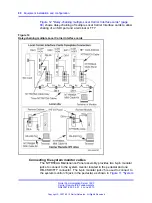
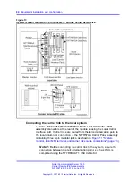
Figure 11 "System monitor, local MMI terminal, and carrier links cable
connections" (page 73)
shows the NT7R57AA Carrier Panel and
NT7R58AA Maintenance Panel assemblies with the system monitor, the
SDI/TTY, and the carrier connections. The NT7R58AA Maintenance panel
assembly connector is used to connect the SDI port and the local MMI
terminal. The NT7R57AA Carrier panel assembly is used to connect the
three carriers.
Figure 11
System monitor, local MMI terminal, and carrier links cable connections
Nortel Communication Server 1000
Carrier Remote IPE Fundamentals
NN43021-555 04.01
4 June 2010
Copyright © 2007-2010 Nortel Networks. All Rights Reserved.
.
Содержание Communication Server 100
Страница 213: ......


