


Carrier Remote IPE fault isolation and correction
161
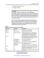
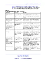
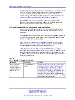
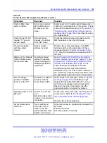
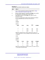
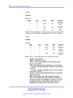
Table 30
Carrier Remote IPE equipment problems (cont’d.)
Symptoms
Diagnosis
Solution
Carrier LEDs show
alarm condition.
One or more carrier
alarm LEDs are on.
No activity on the
carrier.
Alarm Level 2 or 3. Alarm Level 2 allows voice
calls but no new data calls on the carrier. Check
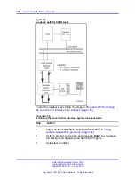
carrier link connections and go to
“Performing the Local Carrier Interface system
loopback tests” (page 168)
to test the link using
the loopback test.
Carrier link is OK but
remote TTY cannot
access system.
Protocol not set
properly or terminal
not in SDI mode.
Check the protocol setup and make sure the
MMI terminal is in the host SDI mode.
No communication
with the system
monitor.
System monitor
address incorrect.
Observe the system messages on the MMI
terminal and check the description of these
messages listed in
. Use this information to locate and correct
the fault.
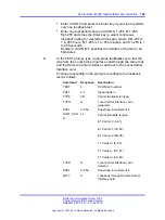
Display on the Remote
Carrier Interface card
shows fault codes.
Card faulty, failed
self-test or problem
communicating with
intelligent peripheral
equipment.
Go to
Procedure 40 “Performing the Remote
Carrier Interface card self-test” (page 171)
and
Procedure 41 “Performing the Remote Carrier
Interface card loopback test” (page 173)
to
check tracking and loopback. Also refer
to Software Input Output Administration
(NN43001-611) () for a list of codes. Based on
the maintenance display codes description, take
the appropriate action and resolve the problem.
Error messages
printed on the MMI
terminal or the TTY.
Hardware or software
problems with the
Carrier Remote IPE.
Note various error messages. Refer to
and Software Input
Output Administration (NN43001-611) () for a
list of these messages and their description.
Based on the code’s description, take the
appropriate action to resolve the problem.
Signaling works but no
talk path.
Carriers are crossed
over.
External loopback left
in place no end-to-end
connection.
Check each carrier and make sure they are not
crossed over. Refer to
link to the Remote IPE module” (page 96)
.
Remove the external loopback.
Amber maintenance
LED is on.
Test is performed
over one or more
carrier in the link.
Alarms disabled. SW1
position 2 set wrong.
Wait until the test is completed and analyze the
test data.
Enable the alarms.
Set SW1 position 2 correctly.
Nortel Communication Server 1000
Carrier Remote IPE Fundamentals
NN43021-555 04.01
4 June 2010
Copyright © 2007-2010 Nortel Networks. All Rights Reserved.
.
Содержание Communication Server 100
Страница 213: ......


