78
Equipment installation and configuration
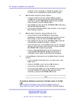
connector. If it is necessary to change the gender at the
terminal, use the appropriate compact gender changer.
2
MMI terminal connection using a modem:
•
If using a modem to connect a distant MMI terminal to
the MMI port on the local I/O panel, plug the DB-9 female
connector of the NT7R66BA MMI Cable into the P3 DB-9
male connector of the NT7R67DA cable.
•
Plug the DB-25 male end of the NT7R66BA MMI Cable into a
DB-25F/DB-25M nullmodem.
•
Connect the nullmodem DB-25 male connector to the modem
DB-25 female connector.
3
MMI terminal connection using an A/B switch box:
•
Connect the P3 of the NT7R67DA Local External
Maintenance Cable assembly DB-9 male connector into the
DB-9 female connector of the NT7R66BA MMI Cable.
•
Plug the DB-25 male and of the NT7R66BA MMI Cable into
the A/B switch box DB-25 female C connector.
•
From the switch box, a local MMI terminal can be connected
directly to the A position on the switch box using a standard
DB-25M/DB-25M straight-through cable.
•
As well, a distant MMI terminal can be connected over
a standard DB-25M/DB-25M straight-through cable, a
nullmodem, and a modem to the switch box B position.
4
Terminal/Modem connections over the MSDL Single Terminal
Access:
•
To avoid using the A/B switch box, use three ports on the
MSDL card.
•
Connect one MSDL port to the local MMI terminal.
•
Connect the second MSDL port to a modem.
•
Connect the third MSDL port to the P3 DB-9 male connector
of the NT7R67DA Local External Maintenance Cable
assembly by using the NT7R66BA MMI Cable.
--End--
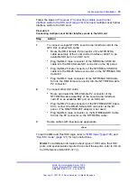
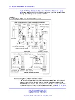
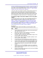
Connecting multiple Local Carrier Interface cards to the SDI
card
Refer to
Figure 27 "Multiple LCIs connection diagram (local site
daisy-chain connection)" (page 199)
to see the SDI connection diagram.
Nortel Communication Server 1000
Carrier Remote IPE Fundamentals
NN43021-555 04.01
4 June 2010
Copyright © 2007-2010 Nortel Networks. All Rights Reserved.
.
Содержание Communication Server 100
Страница 213: ......


