Local equipment installation
83
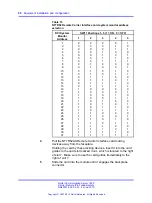
3
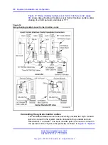
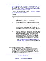
Connect J5 modular jack of the top NT7R58AA Maintenance
Panel assembly in
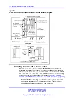
Figure 13 "System monitor connections at
the local site and the Carrier Remote IPE" (page 84)
to the J6
modular jack of the next system monitor towards master system
monitor using the NT8D46AL modular cable.
4
Connect J6 modular jack in the bottom NT7R58AA Maintenance
Panel assembly to the J5 modular jack of the next slave
system monitor away from the master system monitor using the
NT8D46AL cable.
5
Connect J6 modular jack of the slave system monitor to the J5
modular jack of the next slave system monitor outbound (away)
from the master system monitor using the NT8D46AL cable.
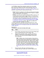
Note: The columns do not have to be daisy-chained in the
sequence according to the system monitor address. The
system monitor daisy-chain is broken when a Local Carrier
Interface card is unplugged from the network card slot.
This causes PWR error messages for polling failure on all
slave system monitors that follow the removed Local Carrier
Interface card in the chain. If possible, connect Local Carrier
Interface cards at the end of the system monitor daisy-chain
after all the local slave system monitors.
--End--
Figure 13 "System monitor connections at the local site and the Carrier
Remote IPE" (page 84)
shows system monitor daisy-chain connections at
local and Carrier Remote IPE sites. The alarm information is sent over the
carrier link from the Remote Carrier IPE to the local system CPU.
Nortel Communication Server 1000
Carrier Remote IPE Fundamentals
NN43021-555 04.01
4 June 2010
Copyright © 2007-2010 Nortel Networks. All Rights Reserved.
.
Содержание Communication Server 100
Страница 213: ......


