


10
ELECTRICAL CONNECTIONS
WARNING:
ELECTRICAL SHOCK, FIRE OR
EXPLOSION HAZARD
Failure to follow safety warnings exactly could
result in serious injury or property damage.
Improper servicing could result in dangerous
operation, serious injury, death or property
damage.
Before servicing, disconnect all electrical power
to furnace.
• Before servicing, disconnect all electrical
power to the air handler.
• When servicing controls, label all wires prior
to disconnecting. Reconnect wires correctly.
• Verify proper operation after servicing.
• Electrical connections must be in compliance with
all applicable local codes and ordinances, and with
the current revision of the National Electric Code
(ANSI/NFPA 70).
• For Canadian installations, the electrical connections and
grounding shall comply with the current Canadian Electrical
Code (CSA C22.1 and/or local codes).
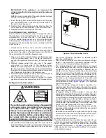
Pre-Electrical Checklist
√
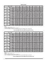
Verify the voltage, frequency, and phase of the supply
source match the specifications on the unit rating plate.
√
Verify that the service provided by the utility is sufficient
to handle the additional load imposed by this equipment.
√
Verify factory wiring is in accordance with the unit wiring
diagram (
). Make sure the connections
didn’t loosen during shipping or installation.
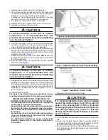
Line Voltage
•
An electrical disconnect must be located within sight
of and readily accessible to the unit
. This switch shall
be capable of electrically de-energizing the outdoor unit.
See unit data label for proper incoming field wiring. Any
other wiring methods must be acceptable to authority
having jurisdiction.
• It is recommended that the line voltage to the unit be
supplied from a dedicated branch circuit containing the
correct fuse or circuit breaker for the unit.
• Overcurrent protection must be provided at the branch
circuit distribution panel and sized as shown on the unit
rating label and according to applicable local codes. See
the unit rating plate.
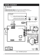
• The installer should become familiar with the wiring diagram/
schematic before making any electrical connections to the
unit. See the unit wiring label or
• Use only copper wire for the line voltage power supply
to this unit. Use proper code agency listed conduit and a
conduit connector for connecting the supply wires to the
unit. Aluminum supply wire may be used if a heater kit is
installed.
• If replacing any of the original wires supplied with the unit,
the replacement wire must be copper wire consisting of
the same gauge and temperature rating.
• Provide power supply for the unit in accordance with the
unit wiring diagram, and the unit rating plate. Use UL listed
conduit and conduit connectors for connecting the supply
wires to the unit and for proper grounding. Field supplied
bushings for the power supply cables must be added to
support and protect the power supply cables.
• All 208/230 Volt units are shipped from the factory wired for
240 volt operation. For 208V operation, remove the lead
from the transformer terminal marked 240V and connect
it to the terminal marked 208V.
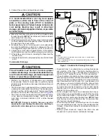
Thermostat Connections
• Thermostat connections shall be in accordance with the
instructions supplied with the thermostat. The thermostat
used with this equipment must operate in conjunction
with any installed accessories. Typical AC and air handler
hookups are shown in
CAUTION:
Isolation must be maintained from the external
Class 2 output of any transformer in a cooling
circuit. Use a thermostat with isolating contacts
to prevent inter-connection of Class 2 outputs.
• Where local codes require that the thermostat wiring must
be routed through a conduit or raceway, splices can be
made inside the unit; however, all wiring must be NEC
Class 1 and separated from incoming power leads.
• The thermostat should be mounted about 5 feet above the
floor on an inside wall. DO NOT install the thermostat on
an outside wall or any other location where its operation
may be adversely affected by radiant heat from fireplaces,
sunlight, or lighting fixtures, and convective heat from
warm air registers or electrical appliances. Refer to the
thermostat manufacturer’s instruction sheet for detailed
mounting and installation information.
• Install the grommet, which is packed with the unit, in the
hole for low-voltage wires. Properly connect the low-voltage
wiring between the thermostat, outdoor unit, and control
board.
NOTE:
When the low voltage wires are positioned
in this grommet, the grommet will prevent chafing and/or
shorting of the low voltage leads.
Grounding
WARNING:
The unit cabinet must have an uninterrupted or
unbroken electrical ground to minimize personal
injury if an electrical fault should occur. Do not
use gas piping as an electrical ground!
This unit must be electrically grounded in accordance with
local codes or, in the absence of local codes, with the National
Electrical Code (ANSI/NFPA 70) or the CSA C22.1 Electrical
Code. Use the grounding lug provided in the control box for
grounding the unit.
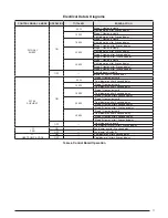
Control Board
The control board in the air handler controls the timing
sequence of the elements. The board is equipped with a 3
second blower on delay and a 15 second blower off delay in
heating and a 40 second blower off delay in cooling.
board modes and actions.
Twinning
These instructions are to be used when connecting two
B64 air handlers (1.5 - 4 ton) to a common single stage A/C


