Nokia 201, Руководство по обслуживанию
FAQ 201 - онлайн руководство, доступное для скачивания бесплатно на {сайт}. Здесь вы найдете все необходимые инструкции по использованию продукта. Просто загрузите его и начните использовать!
Поделиться
Скачать


Отзывы:
Нет отзывов
Похожие инструкции для 201

95
Бренд: iData Страницы: 34

Easy 2
Бренд: M2M Страницы: 88

Yealink SIP-T48G
Бренд: Yealink Страницы: 2

Yealink SIP-T48G
Бренд: Yealink Страницы: 4

Yealink SIP-T46G
Бренд: Yealink Страницы: 38
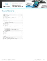
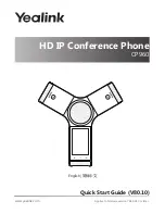
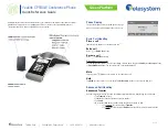
One Talk CP960
Бренд: Yealink Страницы: 4
One Talk CP960
Бренд: Yealink Страницы: 20

One Talk CP960
Бренд: Yealink Страницы: 255

Yealink SIP-T48G
Бренд: Yealink Страницы: 105

T48G
Бренд: Yealink Страницы: 13

CP860 SERIES
Бренд: Yealink Страницы: 77
CP860 SERIES
Бренд: Yealink Страницы: 5
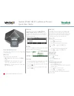
CP930W Telesystem
Бренд: Yealink Страницы: 2

Z110
Бренд: Acer Страницы: 56

JF1 SLIM
Бренд: Light Repute International Страницы: 15

PG-1810
Бренд: Pantech Страницы: 54

au K008
Бренд: KDDI Страницы: 51

au K010
Бренд: KDDI Страницы: 51


