


Use and Maintenance Manual model “H14 V SHAPE”
17
ENGLISH
ENGLISH
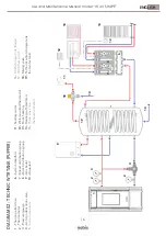
SCHEMA IMPIANTO 03 - COLLEGAMENTO AD ACCUMULO ACQUA TECNICA (PUFFER) + ACCUMULO ACS (BOLLITORE)
1 - 2 - 3 - 4 -
5 -
Termostufa a pellet
Termometr
o
Manometr
o
Valvola anticondensa
Separator
e d’impianto
6 - 7 - 8 - 9 - 10 -
Collettor
e impianto
Gruppo distribuzione miscelato
Gruppo distribuzione in dir
etta
Caldaia a gas
Acquesdotto
11 - 12 - 13 - 14 - 15 -
16 - 17 - 18 - 19 -
1
2
3
4
2
9
11
12
12
13
14
10
18
19
Acqua sanitaria
Cr
onotermostato a par
ete
Riscaldamento a pavimento
Riscaldamento a termosifoni
Valvola a tr
e vie Risc./Sani
Accumulo ACS (Bollitor
e)
Flussostato ACS
Valvola miscelatrice
Accumulo acqua tecnica (Puf
fer)
6
7
8
15
16
17
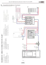
DIAGRAM 03 - TECHNIC WTR. (PUFFER) + DHW T
ANK
1 - 2 - 3 - 4 -
5 -
Thermo pellet stove
Thermometer
Pr
essur
e gauge
Anti-condensation valve
System separator
6 - 7 - 8 - 9 - 10 -
System manifold
Mixed distribution gr
oup
Dir
ect distribution gr
oup
Gas boiler
Aqueduct
11 - 12 - 13 - 14 - 15 -
16 - 17 - 18 - 19 -
Sanitary water
W
all-mounted thermostat
Floor heating
Heating with radiators
Thr
ee-way heating valve
DHW storage tank (Boiler)
DHW flow switch
Mixing valve
Technical water storage tank
(hot water tank)