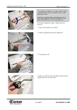
8
Service Manual – SC8000
S uee ee S ste
unctional escri tion
vervie
The squeegee system includes the squeegee assembly, squeegee mounting assembly, squeegee lift weldment
and the squeegee lift cylinder.
7KHVTXHHJHHDVVHPEO\LVPRXQWHGDWWKHERWWRPUHDURIWKHPDFKLQHDQGSLFNVXSWKHZDWHUIURPWKHÁRRU
Two squeegee blades (front and rear) pick up the water and direct it into the vacuum hose which carries it to
the recovery tank. The squeegee lift cylinder raises and lowers the squeegee as appropriate for the operation
being performed.
S uee ee S ste
irin ia ra
Circuit escri tion
For the squeegee system to work, the key switch must be on, the engine must be running and the
Driver Box
must receive a signal from the
Dashboard Panel
via the CAN Bus that the Operator has actuated the scrub
system, vacuum switch (old style control panel) or the vacuum/wand switch (new style control panel).
Fuse, 100A
Relay, Power
Dashboard Panel
Driver Box
J2-5
J2-6
K1
F1
Circuit Breaker, 15A
CB6
Circuit Breaker, 10A
Squeegee Down S2
L2
Squeegee Up S3
L3
K1
B1
3
B
Relay, Power
J2-1
S1
Switch, Ignition
J1-3 CAN +
J1-2 CAN -
J1-10
J1-31
J1-11
J1-27
J1-18
J6-3 CAN +
J6-1 (B+)
J6-2 (B-)
J6-4 CAN -
1
3
2
Drive Pedal Sensor, 5K Ohm
Twisted Pair
Twisted Pair
R1
1
2
1
2
1
87
30
2
1
2
Switch, Recovery Full (opens when the recovery tank is full)
1
2
S2
Battery
12 VDC
Bat -
Bat -
Содержание 56108110 SC8000 48 LPG
Страница 17: ...eneral n or ation Service Manual SC8000 verall i ensions ...
Страница 80: ...irin ia ra u ota n ine 0 lectrical S ste 80 Service Manual SC8000 ...
Страница 110: ...raulic S ste 0 Service Manual SC8000 raulic Sc e atic ...
Страница 123: ...raulic S ste Service Manual SC8000 S ecial ools Hydraulic test gauge w connector 3000 psi range p n 56504516 ...
Страница 150: ...Scru S ste C lin rical 0 Service Manual SC8000 S ecial ools GUDXOLF WHVW JDXJH Z FRQQHFWRU SVL UDQJH S Q ...
Страница 225: ......