2018.11 / m
18
Electric Power Generation
Installation and maintenance
LSA 40
Low Voltage Alternators - 4 pole
4455 en -
Reassembly
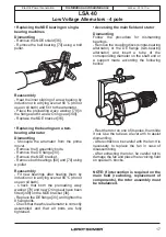
- Follow the dismantling procedure in
reverse order.
Take care not to knock the windings when
refitting the rotor in the stator.
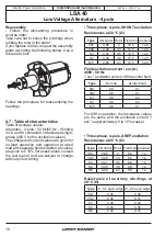
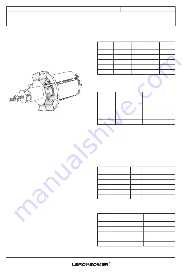
If you replace the fan, respect the assembly
guide according the following bellow. Use a
tube and a bolt.
Follow the procedure for reassembling the
bearings.
4.7 - Table of characteristics
Table of average values:
Alternator - 4 pole - 50 Hz/60 Hz - Winding
no. 6 and M connected in dedicated single-
phase (400 V for the excitation values).
The voltage and current values are given for
no-load operation and operation at rated
load with separate field excitation. All values
are given to ± 10% (for exact values, consult
the test report) and are subject to change
without prior warning.
• Three-phase: 4-pole, SHUNT excitation
Resistances at 20 °C (Ω)
Type
L/N stator Rotor Field coil Armature
VS1
0.66
3
12.5
1.40
VS2
0.48
3.3
12.5
1.40
S3
0.41
3.5
12.5
1.40
S4
0.35
3.8
12.5
1.40
M5
0.28
4.3
12.5
1.40
Field excitation current i exc (A)
400V - 50 Hz
“i exc”: excitation current of the exciter field
Type
No load
At rated load
VS1
0.9
2.1
VS2
0.8
2.1
S3
0.8
2.2
S4
0.8
2.2
M5
0.8
2.1
For 60 Hz operation, the resistance values
are the same and the excitation current “i
exc” is approximately 5 to 10% weaker.
• Three-phase: 4-pole, AREP excitation
Resistances at 20 °C (Ω)
Type
L/N stator Rotor Field coil Armature
VS1
0.66
3
6.6
1.4
VS2
0.48
3.3
6.6
1.4
S3
0.41
3.5
6.6
1.4
S4
0.35
3.8
6.6
1.4
M5
0.28
4.3
6.6
1.4
Resistance of auxiliary windings at
20 °C (Ω)
Type
X1, X2 auxil. wdgs Z1, Z2 auxil. wdgs
VS1
0.45
0.38
VS2
0.36
0.31
S3
0.38
0.33
S4
0.34
0.36
M5
0.32
0.33


