Nice WIDEL Скачать руководство пользователя страница 24

English –

 22

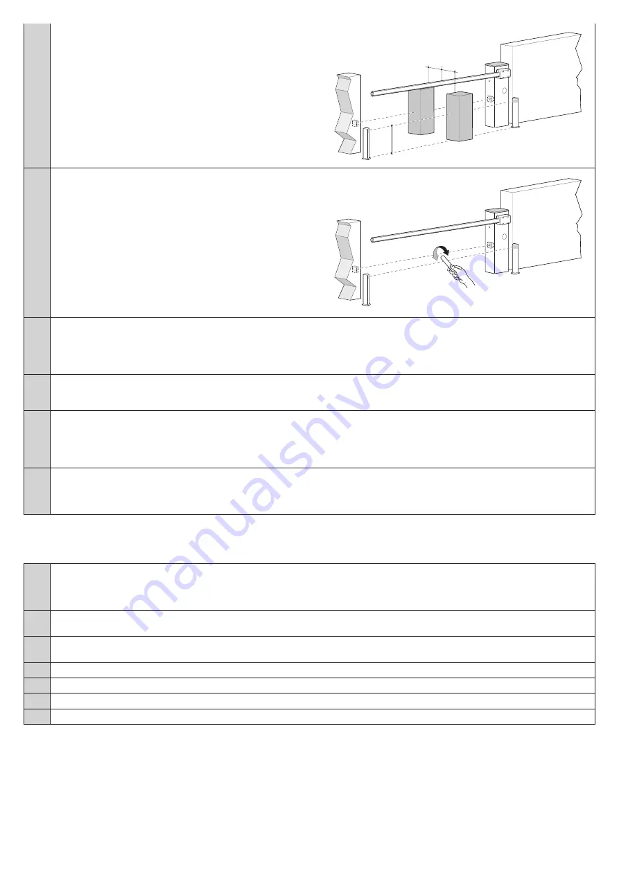
If the test is on two pairs of photocells, the test must first be per-

formed individually for each pair of photocells using 1 testing block 

and then repeated using 2 testing blocks.

Every testing block must be positioned laterally in relation to the 

centre of the boom, at a distance of 15 cm and then moved along 

the entire length of the boom.

During these tests, the testing block must be detected by the pho-

tocells at any position along the entire length of the boom.

300

200

700

500

300

200

700

300

200

700

500

150

150

07.

a - Check that there is no interference between the photocells and 

other devices:

- interrupt the optical axis linking the pair of photocells using a 

cylinder (

diameter

 of 5 cm and length of 30 cm)

- pass the cylinder first close to the TX photocell, then close to the 

RX and lastly at the centre between the two photocells.

b - Check that the device intervenes in all cases, going from active 

status to alarm status and vice versa

c - Check that it causes the intended action in the control unit (e.g. 

a reverse movement during the closing manoeuvre).

300

200

700

500

300

200

700

300

200

700

500

150

150

08.

Check on the safeguard against the lifting hazard: in automations with vertical movement you must ensure that there is no lifting hazard. 

Run the test as follows:

- at a point half-way along the boom, hang a weight of 20 kg (e.g. a sack of gravel)

- send an Opening command and check that during the manoeuvre the boom does not exceed the height of 50 cm above its closed 

position. If the boom exceeds this height it is necessary to reduce the working force by using the FL trimmer (Section 7.1).

09.

If the dangerous situations caused by the movement of the boom have been safeguarded by limiting the force of impact (step 8), the 

impact force must be measured according to EN Standard 12445 and, if the control of the “motor force” is used to assist the system 

for the reduction of the impact force, it is necessary to experiment and, in the end, find the adjustment that provides the best results.

10.

Check the efficiency of the manual release system:

a - place the boom in its closed position and perform the manual release of the gearmotor, making sure that it takes place with ease

b - check that the manual force for moving the boom to the Open position does not exceed 200 N (approximately 20 kg); the force is 

measured perpendicular to the boom and at 1 m from the axis of rotation

c - check that the manual release key is available near the automation.

11.

Check the power supply disconnection system:

a - operate the power disconnection device and disconnect any available back-up batteries

b - check that all the LEDs on the control unit are OFF and that the boom remains still when a command is sent

c - check the efficiency of the manual locking system to prevent any unintentional or unauthorised reconnection

6.2 - Commissioning

Commissioning can take place only after all testing phases have been terminated successfully (par. 6.1).

Partial or “makeshift” commissioning is strictly prohibited.

01.

Prepare and store the technical documentation for the automation for at least 10 years. This must include at least: an assembly drawing 

of the automation, a wiring diagram, an analysis of hazards and solutions adopted, a manufacturer’s declaration of conformity of all the 

devices installed (use the annexed CE declaration of conformity); a copy of the automation system instruction manual and maintenance 

schedule

02.

Affix a label or plate permanently to the barrier mechanism, bearing instructions on how to manually release the gearmotor: use the 

figures included at the end of the User Manual (removable insert)

03.

Using the key switch or radio transmitter, test the Opening and Closing of the barrier mechanism and make sure that it moves in the 

intended direction

04.

Prepare the CE declaration of conformity for the automation system and deliver it to the owner

05.

Give the owner the user manual (tearout insert)

06.

Prepare and give the owner the maintenance schedule

07.

Before commissioning the gate, inform the owner in writing about the attendant residual risks.

Содержание WIDEL

Страница 1: ...EN User installation and safety instructions Electromechanical road barrier WIDES WIDESI WIDEM WIDEMI WIDEL WIDELI WIDES V1 WIDESI V1 WIDEM V1 WIDEMI V1 WIDEL V1 WIDELI V1 Nice...

Страница 2: ...cast in accordance with the following harmonised standards EN 60335 1 2002 A1 2004 A11 2004 A12 2006 A2 2006 A13 2008 A14 2010 A15 2011 EN 60335 2 103 2003 A11 2009 In addition the product conforms to...

Страница 3: ...able connections 17 5 STARTING THE AUTOMATION AND CHECKING THE CONNECTIONS 5 1 Hooking the automation up to the mains 19 6 TESTING AND COMMISSIONING 6 1 Testing 21 6 2 Commissioning 22 7 PROGRAMMING 7...

Страница 4: ...Keep the product away from sources of heat and naked flames Failure to observe the above can damage the product and increase the risk of danger or malfunction If this should happen stop installation i...

Страница 5: ...ted machinery and is therefore manufactured to be integrated into a machine or assembled with other machines in order to create a machine pursuant to Machinery Directive only in combination with other...

Страница 6: ...cally moving doors Operating forces for power operated closures The operating forces exerted by the boom with regard to the risks of crushing and impact are safeguarded against by means of one of thes...

Страница 7: ...5 Force setting trimmer I above 50 5 10 10 02 Depending on the chosen barrier mech anism model proceed as follows on the graph a using the value found above draw a vertical line until it crosses the c...

Страница 8: ...box for barrier mechanism cabinet c box for small hardware d anchors e manual lock release key f Boom cap 2 caps to cover the rubber impact protectors these are found in the box for small hardware g...

Страница 9: ...8 mm 1000 mm 3 WIDE S WIDE M WIDE L To install the barrier proceed as described below 01 Establish the installation position of the various system components e g Fig 2 If the base does not exist start...

Страница 10: ...vel 05 Wait until the concrete hardens usually at least two weeks and then remove the 4 upper nuts of the anchors 06 Fixing the barrier mechanism cabinet a b unscrew the screws and remove the cover c...

Страница 11: ...B in the factory it is anchored in non definitive holes WIDE S WIDE M WIDE L 7 m A Only with 7 m boom place the balancing springs as shown in Figure A If you require RIGHT ORIENTED BOOM with the cabin...

Страница 12: ...model purchased In the factory the balancing spring is anchored in non definitive holes Move the balancing spring attachment into one of the holes on the other arm of the WIDE balance lever based on...

Страница 13: ...English 11 WIDE M WIDE M a b c d e f l 90 i h g...

Страница 14: ...English 12 7 m 7 m WIDE L WIDE L a b c d e f l 90 g h i A A Only with 7 m boom place the balancing springs as shown in Figure A...

Страница 15: ...y from this point a insert them into the free end of the boom if necessary use a rubber mallet and continue with step 10 a Assembly BOOM CONSISTING OF 2 PIECES whole or cut CAUTION With booms consisti...

Страница 16: ...he rubber impact protector and repeat for the other pieces Note The rubber impact protector can protrude about 1 cm from the end of the aluminium profile 1 cm c d put on the boom cap and secure it wit...

Страница 17: ...sitioned anchored so as to guarantee the balancing at 45 WIDE L with 6 7 m boom requires 2 balancing springs positioned anchored so as to have the balancing at 45 a manually release the gearmotor b ma...

Страница 18: ...ge and injury Fig 4 shows the hookup of a typical installation fig 5 shows the connections to be made on the control unit 4 1 Types of electrical cables Fig 4 Table 3 Types of electrical cable see fig...

Страница 19: ...ntion results in opening or closing with the sequence Open Stop Close Stop 7 14 Open Input of normally open NO type for command devices whose intervention results in an opening manoeuvre with the sequ...

Страница 20: ...STMENT TRIMMER LED FCA OPENING LIMIT SWITCH LED LED OK OK LED LIMIT SWITCH LIMIT SWITCH LED OPEN OPEN LED FLASH FLASHING LIGHT LED CLOSED CLOSED LED FUSE FUSE LED P P STEP BY STEP LED MOTOR MOTOR LED...

Страница 21: ...ns Proceed as described below 01 a manually release the gearmotor based on the model purchased b manually move the boom to about half way 45 c manually lock the gearmotor b a c WIDE S WIDE M WIDE L WI...

Страница 22: ...fectively it is necessary that the limit switch triggers at about 20 before the mechanical stopping point is reached if necessary adjust the two cams to set the desired point a b a b e d c c 20 20 LED...

Страница 23: ...Stop of the barrier mechanism and check that the movement corresponds to the commands given it is recommended that you perform several tests to assess the move ment of the boom and whether any errors...

Страница 24: ...in the end find the adjustment that provides the best results 10 Check the efficiency of the manual release system a place the boom in its closed position and perform the manual release of the gearmot...

Страница 25: ...unit the system intervenes both in opening and closing Note Since the motor needs more power at the start of each manoeuvre departure the obstacle detection system is excluded Adjustment it must be ad...

Страница 26: ...iption ON Pre flashing When a command is sent the flashing light starts flashing and after 5 seconds 2 seconds in Manual mode the movement starts OFF Disabled Switch 6 Operation Description ON Flashin...

Страница 27: ...igure below 15 14 13 12 11 10 9 8 7 6 5 24 V 30 V 0 The power supply voltage is 24V 30 to 50 with a maximum available current of 200 mA Red Light Green Light Operation OFF OFF boom closed no transit i...

Страница 28: ...X photocell inside the barrier mechanism cabinet in the space provided 01 Proceed as indicated in the image below a remove the card of the photocell from its box by levering with a screwdriver CAUTION...

Страница 29: ...a mod PS324 back up battery not supplied that in the event of a power failure supplies power to the automation for a specified time refer to the battery instruction manual CAUTION The backup battery...

Страница 30: ...o the Step by Step input is active LED OPEN Problem Solution Off All OK Open input not active On Intervention of Open input It is normal if the one of the devices connected to the Open input is active...

Страница 31: ...switch paragraph 7 2 Use in acid saline or potentially explosive atmosphere No Operating temperature 20 C 50 C Protection class IP 54 Dimensions mm 280 x 178 x 1000 H 320 x 205 x 1000 H 420 x 205 x 10...

Страница 32: ......

Страница 33: ...t of 20 kg for example a sack of gravel halfway along the length of the boom command an Opening manoeuvre and check that dur ing the manoeuvre the boom does not exceed a height of 50 cm above its clos...

Страница 34: ......

Страница 35: ...escribed below In the event of break age or power failure the automation can still be used while waiting for your installer to service the system or for the power to be restored even if it does not ha...

Страница 36: ...www niceforyou com IDV0384A04EN_20 08 2018_DIGITAL VERSION Nice S p A Via Callalta 1 31046 Oderzo TV Italy info niceforyou com...

Отзывы: