51
J. STARTUP AND OPERATION
J.4.2.1. Measuring Air Temperature and
Liquid Line Temperature
Measuring air temperature:
1. Insert a thermometer in the supply air duct as
close to the unit as possible.
2. Insert a thermometer in the return air duct as
close to the filters as possible.
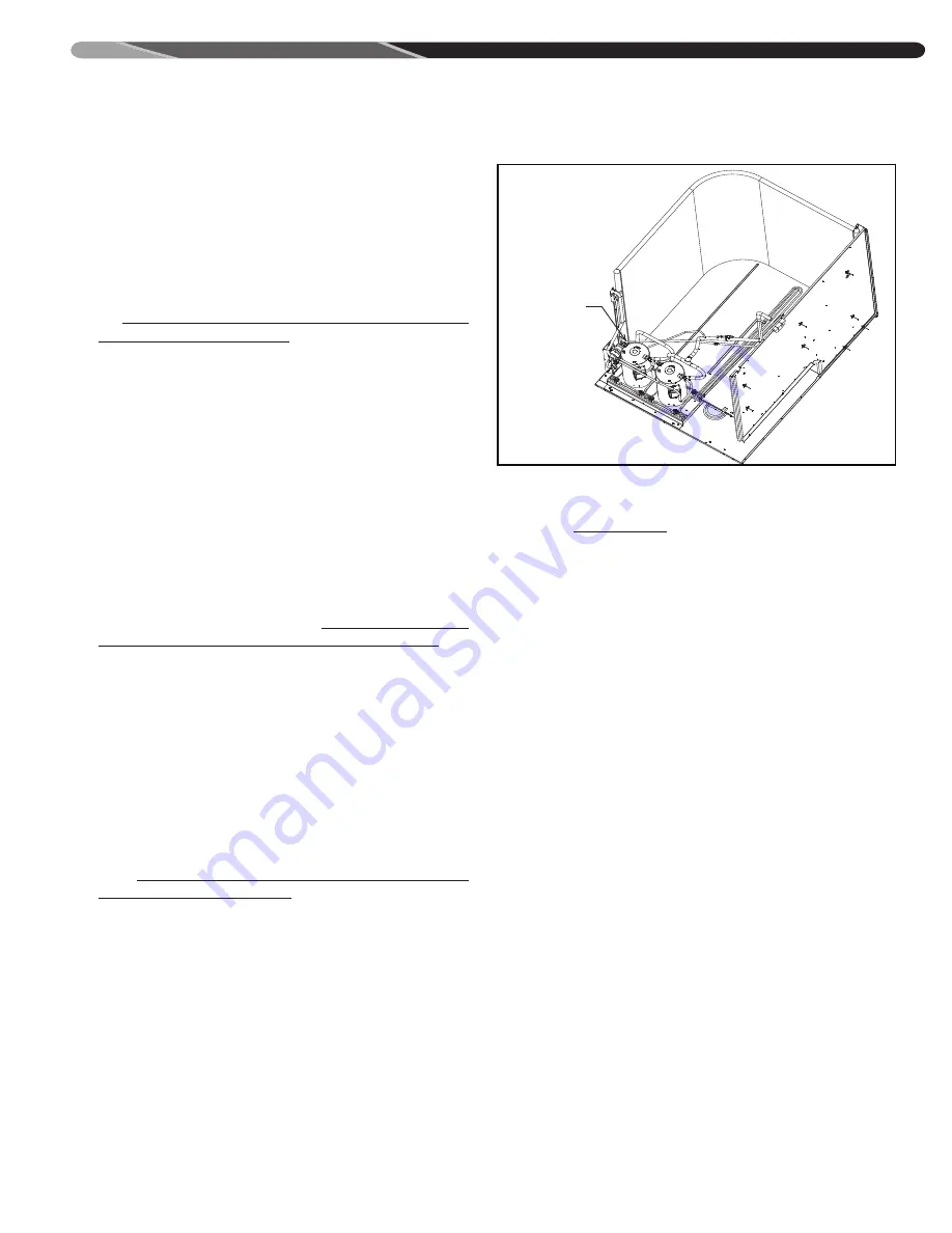
3. If preferred, use the locations shown
in
Figure J.4.2.1. - A: Line Temperature
Measurement Location
instead of the supply/
return ductwork.
4. Operate the unit for a minimum of 15 minutes
in cooling mode.
5. When the thermometer in the supply air duct
stops changing (approximately five minutes),
subtract the return air temperature from the
supply air temperature. This is the cooling mode
temperature difference.
If the measured temperature difference is not
reducing, or if the return air is not reaching the
thermostat set point, the air flow is too low.
Airflow must be increased by either removing
the restrictions in the duct system, or by
changing the air flow. See
Section J.3.2. Air
Flow Measurements and Adjustments
for
changing air flow.
IMPORTANT:
Some high-efficiency filters have
a greater than normal resistance to airflow.
This can negatively affect airflow. BE SURE TO
CHECK THE AIRFLOW if using any filter other
than the factory-provided filter.
Measuring line temperature:
1. Attach a thermometer or thermocouple to the
liquid refrigerant line right after the filter-dryer.
See
Figure J.4.2.1. - A: Line Temperature
Measurement Location.
2. Operate the unit for a minimum of 15 minutes
in cooling mode.
3. When the measurement of the temperature
stops changing (approximately five minutes),
record the temperature.
J.4.3. Measuring Compressor
Electrical Loads
See
Appendix B
towards the end of this manual
for Compressor Electrical Data.
J.5. Checking Heating Operation
J.5.1. Gas Furnace
J.5.1.1. Measuring and Adjusting Supply
Gas Pressures
The maximum gas inlet pressure to the
furnace should be 10.5” WC for natural
gas and 13.0” WC for LP gas the minimum
gas inlet pressure for purposes of input
adjustments to the furnace should be 5.0” WC
for natural gas and 11.0” WC for LP gas.
The inlet pressure tap is on the input side of the
gas valve. A calibrated manometer is required to
measure gas pressure readings accurately.
1. Ensure the gas is shut off to the furnace at the
manual gas valve installed outside the unit.
2. Remove the inlet pressure tap plug using a
3/16” allen wrench; see Figure G.1.4. –A.
3. Install a 1/8” NPT pressure tap fitting and
tighten using a 7/16” open end wrench.
4. Connect manometer using 1/4” I.D. hose over
the pressure tap fitting.
5. Turn on the gas supply and operate the
furnace and all other gas-fire units on the same
gas line as the furnace.
6. Note or adjust the inlet gas pressure to give:
A: 5” - 10.5” W.C. for natural gas
B: 11” - 13” W.C. for LP gas
MEASURE HERE
ST-A1273-55-00
Figure J.4.2.1. – A: Line Temperature Measurement
Location
Содержание Climate Master RGED Series
Страница 2: ...2 62 ...
Страница 88: ...88 P APPENDICES Appendix C Air Flow Performance Data ...
Страница 90: ...90 P APPENDICES Appendix C Air Flow Performance Data Cont ...
Страница 92: ...92 P APPENDICES Appendix C Air Flow Performance Data Cont ...
Страница 94: ...94 P APPENDICES Appendix C Air Flow Performance Data Cont ...
Страница 159: ...159 ...


