XPS-RL
Quick Start
When all stages are added to the stages.ini file, build the system using the web tool
“
Manual Configuration
” under the main tab “
System
”. In this tool, the stages get
assigned to positioners and the positioners get assigned to motion groups. Please refer to
chapter 6.3 (in the XPS-RL User's Manual) for details on the different motion groups
and their specific features. The group name and positioner name can be any user given
name. Once the system has been built, all system information is stored in a file called
system.ini. Also, the system.ini file is located in the Config folder of the XPS-RL
controller and can be viewed or edited from the Web Tool text editor under “
Files
”
→
“
Configuration
files
”.
The following describes the different steps needed to add a stage, to modify the stage
parameters and to build a manual configuration. Chapter 4.0 in the XPS-RL User's
Manual provides further information about some of the steps described here.
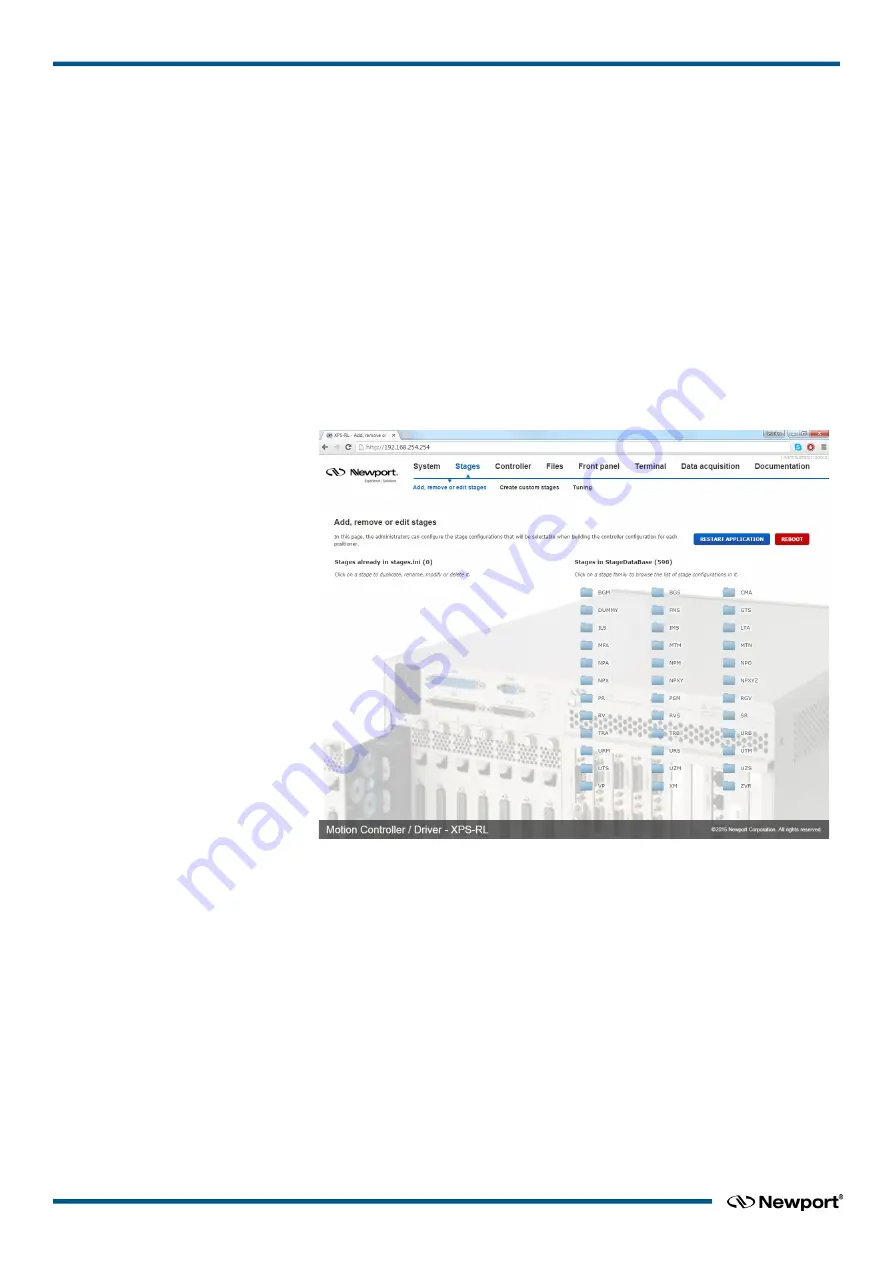
Once you are logged in as Administrator, click on “
Stages”
and then click on “
Add,
remove or edit stages
”.
1.
The following screen appears:
2.
Click on the family name from the Stages in StageDataBase list and a pop up
window appears.
3.
Click the part number corresponding to your hardware.
4.
Select the driver (corresponding to your hardware) and configuration.
For all continuous rotation stages, you can choose between a “regular” stage
configuration and a “Spindle” configuration. A Spindle is a specific rotary device
(no indexing) with a periodic position reset at 360° (by default), meaning 360°
equals 0°. When defining the stage as Spindle in the stages.ini, you must assign this
stage also to a Spindle group in the system configuration and vice versa. For details
about Spindles, please refer to section 6.3 in the XPS-RL User's Manual.
For some stages, you can choose between “regular” initialization or LMI (Large
Move Initialization). The LMI method produces a larger movement of the stage for
commutation and could be used if “regular” initialization fails.
5.
The box “
Use ESP Compatibility for Hardware detection
” is checked by default.
If your stage has an ESP chip inside (see the ESP-compatible sticker on the stage)
EDH0367En1021 — 12/17
22


