Newport OPHIR EA-1 Скачать руководство пользователя страница 6


On the sides: 


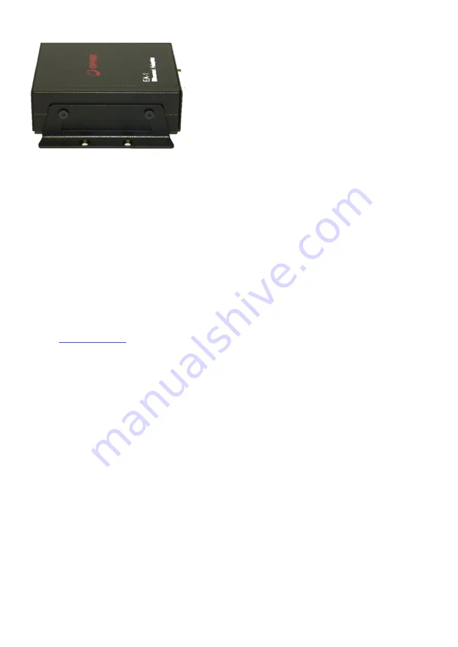
Two M3 mounting holes are provided along each side of the device allowing attachment of an optional 
bracket (as shown in the illustration above). The bracket makes it easier for the customer to attach the 
device into his mechanical system. A set of two brackets and four screws are supplied with the device. 

 
Full device specifications are included in Appendix A below. 

Package Contents: 

The EA-1 package includes the following items: 


EA-1 adapter 


Ethernet cross cable (for initial configuration) 


USB-A to USB-Mini-B cable (for initial configuration) 


Ophir 12v DC power supply 


2x mounting brackets, 4x M3 screws for attaching the brackets to the device, 1x Allen Key 

 
The 

“OphirEthernetApp”

 PC application and drivers for using the USB Virtual COM Port are available on the Ophir 

website

www.ophiropt.com

, search for “EA-1” and “Software”. 

 
The device can be powered either via ‘Power over Ethernet’ (PoE) if available, or via the 12-24v DC input.  

Connection Protocols: 

There are four ways to connect to the device: 


Telnet 


HTTP  


UDP 


USB Virtual COM Port 


Telnet: 

A Telnet connection can be used to send commands and receive back replies from the device. The connection is 
established by using the device’s IP address. The host device (for example, a PC) is the “client” and the EA-1 device is 
the “server”. This type of connection can be used manually from a Telnet terminal, or can be programmed into the 
user’s software application to add automation, in much the same way as using a COM port. This type of connection 
protocol is used in the 

“OphirEthernetApp”

 PC application to control the device. Details are listed later on in this 

document. 

 
HTTP: 

Using a web browser, a connection can be established to the device which allows basic configuration, sending 
commands, monitoring power from the sensor, and viewing general information about the device. The user needs to 
enter the IP address in the browser and a connection is made to the device. A top level “web-page” is displayed with 

Содержание OPHIR EA-1

Страница 1: ...EA 1 Ethernet Adapter USER MANUAL OPHIR OPTRONICS www ophiropt com photonics EA 1 ETHERNET ADAPTER...

Страница 2: ...ting the User Device Name 14 Setting the Mains Frequency 14 Returning to Factory Default Settings 15 Chapter 3 HTTP and the Built In Web Server 16 Connecting to the built in web server 16 Using the bu...

Страница 3: ...oing Commands 35 Power Measurement Commands 35 Energy Measurement Commands Thermopile Sensors 37 Wavelength Commands 38 Continuous Send Commands 40 Misc Commands 41 Commands for Pyroelectric PD C Sens...

Страница 4: ...mple opening a Telnet connection or using the USB port refer to a PC running Windows 7 Instructions for a PC running XP or newer versions of Windows are similar or identical in most cases but minor va...

Страница 5: ...1 supports Ophir thermopile photodiode pyroelectric PE C and PD10 series sensors The EA 1 device is supported by a special PC Application OphirEthernetApp or by Ophir s StarLab software package Physic...

Страница 6: ...er over Ethernet PoE if available or via the 12 24v DC input Connection Protocols There are four ways to connect to the device Telnet HTTP UDP USB Virtual COM Port Telnet A Telnet connection can be us...

Страница 7: ...ct to the device separately from the Ethernet for configuration purposes This connection can be used to query or set the IP address for the first time or to switch between dynamic and static IP addres...

Страница 8: ...ct to the device via a network with this IP address Conversely if the IP address is changed by the customer to a new value for example 172 16 16 49 as in the examples below it will still be possible t...

Страница 9: ...ay 172 16 16 1 Note In order to connect to the device using a PC it may be necessary to first set the PC to a static IP address Instructions for doing this are shown in Appendix 2 below The following...

Страница 10: ...e for example 172 16 16 49 Note At present there is no option to switch on DHCP Dynamic IP address allocation using a button this can be done using other methods see below or by typing the command ND...

Страница 11: ...ernatively open windows explorer and navigate to the folder C windows system32 cmd exe or the equivalent and click on the icon or set up a shortcut to cmd exe and place it on the desktop Once the comm...

Страница 12: ...known or when connecting the device directly to a PC network port is not be possible The way to do this is to connect via USB which establishes a connection to the PC via a Virtual COM Port VCP The dr...

Страница 13: ...1 Ethernet Adapter provides the option to use Dynamic IP Address allocation When enabled after the EA 1 powers up it sends a request to the local network requesting a free IP address and other IP sett...

Страница 14: ...above Once this is done the user command DN can be used to query or change the device name The name can be up 30 characters long This command is described more fully in the section on User Commands se...

Страница 15: ...onnectors from the device then unscrew the two screws on the left and right of the panel where the D15 sensor socket is located and then pull the PCB out along with the D15 panel Once removed press do...

Страница 16: ...ached sensor Connecting to the built in web server The example give below refers to a device with IP address 172 16 16 49 Open the web browser for example Internet Explorer and type http 172 16 16 49...

Страница 17: ...al To view the power being measured by the attached sensor return to the Start Page and click on the Power Monitor button The following page will be displayed The latest power measurement will be disp...

Страница 18: ...able or via the 12 24v DC connector The sensor is attached to the adapter via the D15 plug Alternatively the device can be connected to the PC via USB The device uses a USB Virtual COM Port The driver...

Страница 19: ...will open one for each selected sensor The main window allows the user to control all main features of the attached sensor and to view measurements Power Display and Statistics The power or energy bei...

Страница 20: ...engths or regions depending on the sensor being used In the example below the laser options are CO2 10 6um YAG 1 064um or VIS around 532nm But other sensors may have other regions defined Choose the a...

Страница 21: ...wavelength value using the scroll bars or by typing the value in the window as for the Add option above Then click on OK to finalize the choice of wavelength In order to remove one of the existing 6 f...

Страница 22: ...front of each command as it is added automatically by the application A detailed list of user commands is added below Measuring Energy Some thermopile sensors offer single shot energy measurements in...

Страница 23: ...to select LOW MEDIUM or HIGH The default threshold is MEDIUM In order to increase or decrease the default threshold by a factor of 3 choose HIGH least sensitive triggering or LOW most sensitive trigge...

Страница 24: ...the device Note that the first time the DHCP mode is switched on the IP address will probably change the next time the device is powered up The User Device Name can also be added edited or removed us...

Страница 25: ...available and necessary the software will continue with the upgrade automatically Note Do not disconnect the communications or power cables while the firmware is being upgraded Firmware upgrade takes...

Страница 26: ...he latest version is available on the Ophir Website Log Files and Buffer Files The OphirEthernetApp application automatically creates log files while the sensor window is open and the sensor is measur...

Страница 27: ...is a useful way to check which commands are being used by the application and as a way to provide examples when writing custom software to talk to the device It is also useful for debugging in case t...

Страница 28: ...application starts up or when pressing the Search button Customers can also incorporate a similar search using the UDP protocol into their own software in order to detect any Ophir devices connected t...

Страница 29: ...commands and receive replies as an alternative to Telnet See details below in chapter Details of User Commands Summary of TCP Port Numbers By convention TCP uses the following port numbers Connection...

Страница 30: ...EA 1 are terminated by CR LF Replies from the EA 1 begin with a symbol ASCII code 0x2A if there are no errors Replies from the EA 1 begin with a symbol ASCII code 0x3F if there is any kind of error fo...

Страница 31: ...6 letter prefix we have defined for UDP receives XXXX the same user defined string as defined above to check which response is from which command 1 23 is the received data to this command See details...

Страница 32: ...ROM Values are entered and returned in format 172 16 16 49 When setting a new value replies SAVED need reset and saves the value in the local EEPROM to be used after the next reset If the value entere...

Страница 33: ...cated and counts down continually from the moment the IP address is allocated with precision of one second In most cases the device is not likely to be connected to the network for many days at a time...

Страница 34: ...by replying before performing the reset Note When using the USB Virtual COM Port connection it is recommended the channel be closed in the support software immediately after sending this command other...

Страница 35: ...led either a bad zero value was measured or failed to write values to EEPROM ZEROING COMPLETED CR zeroing completed successfully and should now be saved using ZS Zero Save ZS ZS CR status CR LF Saves...

Страница 36: ...Set desired setting e g power scale using WN command b Save chosen settings using HC S command c If the incorrect parameter is sent PARAM ERROR is returned Force Power Command FP FP CR CR Forces senso...

Страница 37: ...uring energy SE returns OVER The SE command will repeatedly return the last energy measurement until a new energy pulse arrives the EF flag can be used to determine if a new energy measurement has arr...

Страница 38: ...f the device is ready to receive the next pulse of energy Wavelength Commands This section is relevant for all types of sensors GENERAL INFORMATION ON WAVELENGTH CONFIGURATION COMMANDS Ophir sensors a...

Страница 39: ...the first available favorite wavelength corresponding to index 1 971 is the second available favorite wavelength 532 is the third available favorite wavelength NONE indicates that the following 3 favo...

Страница 40: ...2 command and is terminated by sending the CS 1 command or by sending any other command Once Continuous Send mode is stopped the receive buffer inside the PC or host device must be flushed before try...

Страница 41: ...anently responds 1 Note Factory default is polling enabled the result of disabling is that if a sensor is swapped over the software firmware and host application will not be aware of the change and wi...

Страница 42: ...ata rates up to 10Hz See details above The commands supported are FE EF SE For higher performance and in particular for higher data rates when using fast pulsed lasers use the Continuous Send mode ins...

Страница 43: ...his mode energy data is returned in a simple ASCII format with 4 significant digits Data is terminated with the Line Feed Carriage Return characters in a similar way to responses from a regular comman...

Страница 44: ...de In Binary Mode data is delivered in large blocks A block consists of a 16 byte header followed by multiple data packages 8 bytes each The header contains information about the number of bytes inclu...

Страница 45: ...1 Byte_6 FLOAT Value energy or frequency byte 2 Byte_7 FLOAT Value energy or frequency byte 3 Most significant 4 OTHER MODES At present the CS modes defined are as described above In addition there ar...

Страница 46: ...sample per pulse up to 40kHz Binary CS mode A to D Resolution 12 bits no sign Electrical accuracy 0 25 new 0 5 after 1 year Electrical input noise 2mV Max data rate every pulse Command Mode 10Hz Max d...

Страница 47: ...ctions Local Area Network Properties Select Internet Protocol TCP IP and click on Properties Select Use the following IP Address set as follows IP address 10 0 0 3 Subnet mask 255 255 255 0 Default ga...

Страница 48: ...may not be displayed Double click or right click and choose properties to open its properties screen Select Internet Protocol Version 4 TCP IPv4 and click on Properties Select Use the following IP Add...

Страница 49: ...settings to match the PC s existing IP address or to restore the EA 1 device to its default IP address follow the instructions in the section above Setting up a static IP address in the Configuration...

Страница 50: ...ge the IP address to match the IP address of the PC but 1 or 1 in the last digit For example 172 16 18 51 do NOT use the exact same address as obtained above from the PC 172 16 18 50 Press Save h Set...

Страница 51: ...ected in the Available Devices list Add the device to the list of My Devices by clicking Add See full instructions in the StarLab Manual m The user should be aware that the next time the PC is started...

Страница 52: ...ther to use shielded or unshielded cable and whether to use non isolated cable where the ground shield is shorted all the way through from one end to the other or isolated cable where the ground is no...

Страница 53: ...hanges in chapter 6 v7 11 May 17 PC app rev 1 12 firmware v1 12 Added details of UDP connection protocol in commands section Minor corrections in commands section v8 1 Jun 17 PC app rev 1 12 firmware...

Отзывы: