System
Components
33
Once connected to the mirror head and to the wall outlet, the FSM-CD300B
controller/driver may be turned on using the POWER switch located on the
left side of the front panel (see
Figure 16
).
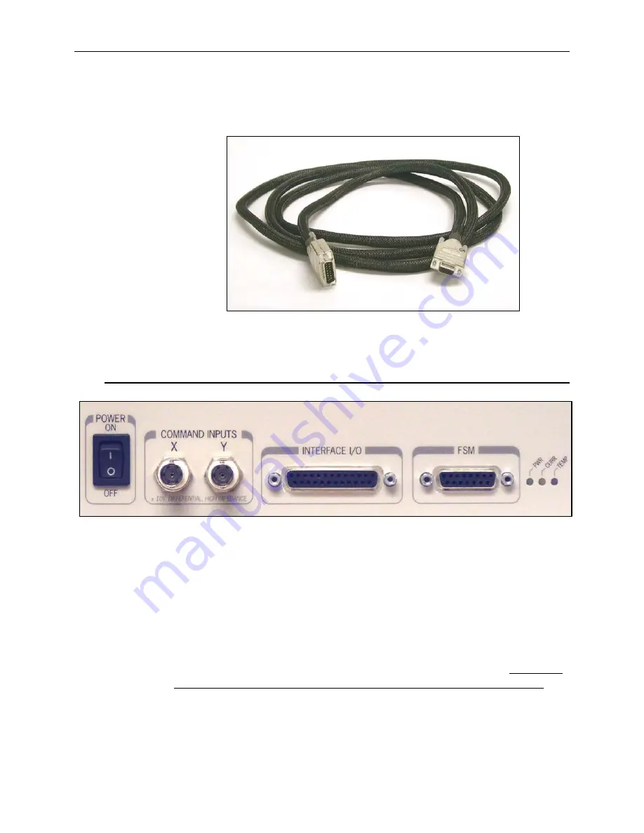
Figure 15: 15-pin interface cable from controller to mirror head.
6.3 Command
Inputs
Figure 16. Front panel I/O connections.
Control voltages called “Command Inputs” are used to direct the mirror to
specified angular positions around two orthogonal axes. These voltages are
normally applied to the two BNC connectors labeled COMMAND INPUTS
X and Y on the front panel, but can also be applied to the 25-pin INTER-
FACE I/O connector on the front panel. Please see
Figure 16
. Scaling is
set so that ±10V DC offsets correspond to the full-scale motion of ±1.5
°
(±26
mrad) mechanical angular range on each axis. A command voltage of zero
will bring the mirror to the powered-on null position for that axis. The X and
Y inputs are differential. Neither lead of the BNC connector is grounded.
Certain FSM system output results (overshoot, settling time and point-to-
point travel path) are dependant upon the input waveform, amplitude and
frequency of the signal. Due to the many possibilities, customers are
encouraged to experiment with their particular drive signal parameters when
Содержание FSM-300
Страница 1: ...FSM 300 Fast Steering Mirror FSM CD300B Controller Driver User s Manual...
Страница 2: ......
Страница 3: ...EU Declaration of Conformity 3...
Страница 4: ......
Страница 9: ...9...
Страница 10: ......
Страница 26: ...26 System Components Figure 9 Detailed Drawing of FSM 300 Mirror Head Housing...


