background image

4

15272 Newsboy Circle
Huntington Beach,  
CA 92649


 Phone: 714-751-0488  

                                     Fax: 714-372-7930 

     E-Mail: [email protected]

PoweringTheNetwork.com

3.2 UPS Module

The UPS module provides utility power to the load when the line is qualified. An automatic voltage regulator (AVR) is 

embedded to provide stable power to the load and instantly switches to emergency backup power during utility power 

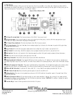
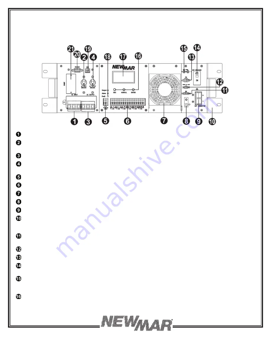
failure or interruption. The front panel view is shown below.

Figure 2: Front Panel of UPS 


AC Input Terminal Block: 

This terminal block is the UPS AC line power input.

 AC Input Breaker: 

This circuit breaker is an on/off switch for the line power into the UPS that also provides input  

protection. It must be switched on for proper UPS operation.


AC Output Terminal Block: 

This terminal block is the UPS AC power output.


AC Output Breaker: 

This circuit breaker is a resettable protective thermal circuit breaker to protect UPS output from 

overload and short circuits.


Input Contact: 

To activate a programmable alarm by shorting this input contact, see section 5.5.9.


Dry Contact: 

Six sets of dry contacts energize when a programmable event occurs, see section 5.5.9.


Internal Fan: 

The fan is to cool down the inside temperature of the UPS and is easily replaced for maintenance.


GND: 

This connector is the permanent ground of the UPS.


Battery Connector: 

The battery connector is to connect external batteries.


Mounting Bracket & Handle: 

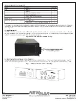
The Rugged UPS Series is for mounting in a 19’’ cabinet. For convenience, handles are  

provided for people frequently moving the unit. Mounting hardware includes (quantity 8): M4 x 3mm Flat Head, Phillips, 

S.S.


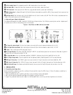
Battery Temperature Connector: 

This probe monitors battery temperature. The temperature probe connector must be 

plugged into the UPS for normal operation. The other end should be firmly attached to the terminal of the battery.


External FAN Connector: 

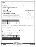
To provide DC Power (48V DC, 3 Amp Max) to an optional cabinet 48V DC fan.


MBS Control Connector: 

This connector provides power to control the MBS unit.


Battery Breaker: 

This over-current protection acts as an ON/OFF switch for the battery power. It needs to be ON for 

proper UPS operation.


Battery Voltage Test Points: 

The test points allow you to measure battery voltage. They accept 2 mm diameter test 

probe tips. The battery circuit breaker must be ON before measuring voltage. 

CAUTION:

 The battery voltage test points 

are NEVER to be used as a power outlet.


Function Keys: 

These buttons operate and control the LCD panel.

Содержание AC UPS Series

Страница 1: ...1 System Architecture 4 5 6 RS232 USB interface 15 3 2 UPS Module 4 5 7 Optional SNMP card 23 3 3 MBS Module Optional 5 6 SPECIFICATIONS 23 4 INSTALLATION 5 6 1 Line Mode Specifications 23 4 1 Unpack...

Страница 2: ...in a risk of electric shock or fire 4 To reduce risk of electric shock disconnect all wirings before attempting any maintenance or cleaning Turning off the unit will not reduce this risk 5 CAUTION On...

Страница 3: ...e Power Supply UPS System and optional Manual Bypass Switch AC UPS BP that provides backup power when the line is unqualified These components should be mounted inside an enclosure to provide protecti...

Страница 4: ...ion 5 5 9 Internal Fan The fan is to cool down the inside temperature of the UPS and is easily replaced for maintenance GND This connector is the permanent ground of the UPS Battery Connector The batt...

Страница 5: ...k The output power connects to the terminal block marked with AC OUT Switch This switch selects UPS or bypass output AC Output Breaker This circuit breaker labeled OUTPUT is a resettable protective th...

Страница 6: ...ease immediately notify your carrier agent and the supplier who prepared your shipment 4 2 Mounting the UPS The UPS unit can be placed in a rack with no other parts needed It can be rack mounted or se...

Страница 7: ...2 cables marked as UPS IN and UPS OUT Connect these cables from MBS to the respective connectors on the UPS 2 Connect the AC input wires to the AC input terminal blocks on the MBS Ensure proper polar...

Страница 8: ...ed the UPS will transfer to line mode with the output LED ON to show UPS is running from utility power Note If the UPS keeps switching between inverter and line mode because of a noisy line the settin...

Страница 9: ...P xxxxVA 9 O P P xxxxWatt 10 Load xxx 11 Mode xxxxx 12 InvEV xxxxx 13 InvTM xxxx xH 14 BukEV xxxxx 15 BukTM xxxx xH 16 BstEV xxxxx 17 BstTM xxxx xH 18 C1 Off or On C2 Off or On 19 C3 Off or On C4 Off...

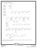
Страница 10: ...e 714 751 0488 Fax 714 372 7930 E Mail techservice newmarpower com PoweringTheNetwork com Figure 10 Setting and Control Page Pressing the ESC SCROLL and ENTER buttons to navigate through the menus and...

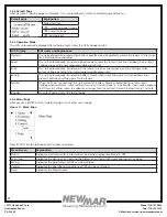
Страница 11: ...voltage when output voltage achieves the user programmable preset limit Battery The unit automatically transfers to battery mode when input line power is unqualified or not present Batteries provide p...

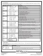
Страница 12: ...has been in battery mode The total time duration the unit has been in battery mode since the latest reset The number of times the unit has been in buck mode The total time duration the unit has been...

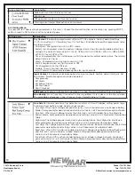
Страница 13: ...ed as below User program Ext Alarm Ext Battery Alarm Ext Fan Failed Door Unlocked AVR Feature Enable or disable Buck and Boost function Factory default setting is enable Line Qualify Set AC recovery t...

Страница 14: ...ustable range is 0 480 min with 15 min increment of each click by pressing SCROLL button The default value is 120min Default UPS Restore factory settings of UPS Default SNMP Restore factory settings o...

Страница 15: ...ool HyperTerminal in Windows device can communicate with computer Follow below steps to step up HyperTerminal Step 1 The path of HyperTerminal communication tool is Programs Accessories Communications...

Страница 16: ...Step 6 The Name of Unit Properties screen will pop up as shown in Figure 17 Click on the Settings tab Select all columns as below figure and click ASCII Setup button Figure 16 HyperTerminal Screen Fi...

Страница 17: ...SETUP 60 CONTACT C1 Current Setting is ON BATT 0 Set to ON BATT 1 Set to LOW BATT 2 Set to TIMER 3 Set to ALARM 4 Set to FAULT 5 Set to OFF 6 Set to DISABLE 0 MAIN MENU 6 PROGRAMMABLE CONTACTS SETUP...

Страница 18: ...nu numbers the line status the unit s output status and any faults or alarms that may be present Figure 20 Main Menu Screen BTS Manual Bypass Switch MBS UPS Model ID xxxxxxxxxxxxxx 0 MAIN MENU 1 Unit...

Страница 19: ...re version Main Firmware Version Main board firmware version Hardware Version Hardware version IP Address UPS IP address Line Status Current Status Output Status Current Status Contact Status Current...

Страница 20: ...e the latest RESET BUCK Event The number of times that BUCK function activates BUCK Timer Total time that the BUCK function activates since the latest RESET BOOST Event The number of times that BOOST...

Страница 21: ...tions to factory default value 47 Set Date Adjust the date 48 Set Time Adjust the time 49 Change Password Change password The factory default password is 1111 Note The password can only be changed in...

Страница 22: ...Mode Line to Battery 100VAC 88 120V AC 88V AC 88 120V AC 56 Boost Low When input voltage drops between Boost Back point and Boost Low point unit will transfer to Boost Mode only when AVR is enabled No...

Страница 23: ...1 0 Nominal battery voltage 48V DC 24V DC Utility Voltage Waveform Sinusoidal utility or generator Utility qualify time setting 3 10 30 seconds adjustable Nominal Input Voltage 120V AC AVR function E...

Страница 24: ...able Peak Efficiency 90 No Load Power Consumption 28W 48V DC 28W 24V DC THD Bat mode 3 Full resistive load Load crest factor 3 1 rated load Overload protection 5s 125 150 load 60s 110 125 load Output...

Страница 25: ...AGM 28 2 56 4V DC 27 0 54 0V DC Battery Temperature Control Charging voltage is compensated according to battery temperature 2 5mV 3 0mV 3 5mV 4 0mV per cell per C compensated coefficient adjustable C...

Страница 26: ...lace MBS UPS does not return back to Line mode Line power is missing Verify if power cord from UPS IN on MBS is properly connected to the AC input terminal blocks on UPS Verify if the UPS INPUT circui...

Страница 27: ...bad temperature probe connected Only use factory supplied temperature probe reading approximately 15 000 OHMS 25 C 77 F LCD text is not readable UPS fault Return to repair center Password access is NO...

Страница 28: ...e 24V DC 100Ah min Backup Time 24V DC 200Ah min AC UPS 24 700 10 1807 3613 20 858 1807 30 561 1205 40 378 869 50 306 703 60 253 581 70 197 442 80 155 383 90 137 337 100 121 294 9 WARRANTY AND FACTORY...

Отзывы: