


78
LH
(”Reset”)
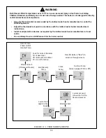
FIGURE 14.3: RESET BUTTON
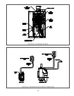
Condensate Trap
– The condensate trap allows condensate to leave the boiler while containing flue gasses. In the event that
this trap becomes blocked, condensate will start to back up in the trap. To prevent a rising condensate level from backing up
into the heat exchanger, both a ground wire and the flame rod wire are bonded to this trap in such a way that an abnormally high
condensate level will conduct flame current directly to ground (Figure 10.5). The boiler control will interpret this as a loss of
flame and enter a Hold. See Figures 7.25 or 13.3 for trap location.
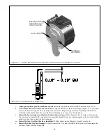
Combustion Fan
– The combustion fan pushes air-fuel mixture into the burner and the speed of this blower determines the firing
rate. There are two electrical connections at this fan:
• 120V Plug – Supplies 120VAC Power to the Fan
• Speed Control Plug
- Delivers a PWM (speed control) signal from the boiler control to the fan. This plug also includes
` tachometer connections so that the boiler control can monitor the actual fan speed.
In the event that there is 120volts at the boiler, but no signal at the speed control plug, this fan will run at its maximum speed.
Specific causes of this include:
• Disconnected speed control plug
• Loose J2 Plug
• Loose L2 or L3 Plug
• Defective 24V Transformer
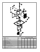
Gas Valve
– The gas valve used on this boiler has either one or two 24VDC coils (the gas valve used on all boiler models is
redundant). The gas valve output from the boiler control is 24VAC. A rectifier module is installed between the gas valve and the
wiring harness on the 80, 100 and 120 models (Figure 11.4a). The rectifier is built into the gas valve plug itself on the 150 and
180.
Содержание GHE Series
Страница 10: ...9 Figure 5 1 Wall Layout Mounting Hole Location...
Страница 11: ...10 Figure 5 2 Boiler Mounting Bracket Installation Boiler Wall Mounting...
Страница 17: ...16 FIGURE 7 4 WALL PENETRATION CLEARANCES FOR PVC VENT PIPE...
Страница 34: ...33 FIGURE 7 24 INSTALLATION OF IPEX AND DIVERSITECH CONCENTRIC TERMINAL THROUGH ROOF...
Страница 41: ...40 FIGURE 9 2 NEAR BOILER PIPING HEATING ONLY BOILER LOOP PIPING SHOWN SHADED...
Страница 42: ...41 FIGURE 9 3a NEAR BOILER PIPING HEATING PLUS INDIRECT WATER HEATER...
Страница 43: ...42 FIGURE 9 3b NEAR BOILER PIPING HEATING PLUS INDIRECT WATER HEATER...
Страница 47: ...46 This page is intentionally left blank...
Страница 50: ...49 FIGURE 10 2 LINE VOLTAGE FIELD CONNECTIONS FIGURE 10 3 LOW VOLTAGE PCB TERMINAL CONNECTIONS...
Страница 52: ...51 FIGURE 10 4a 120V LWCO FIELD WIRING FIGURE 10 4b 24V LWCO FIELD WIRING...
Страница 54: ...53 FIGURE 10 6 INTERNAL WIRING CONNECTIONS DIAGRAM...
Страница 55: ...54...
Страница 62: ...61 Lighting and Operating Instructions...
Страница 82: ...81 FIGURE 14 6 CONTROLS LOCATION FIGURE 14 7 PRESSURE SWITCH TUBING CONNECTIONS...
Страница 87: ...86 Blower Gas Valve Assembly for 150 180...
Страница 90: ...89...
Страница 103: ...102...
Страница 104: ...106914 02 8 16 New Yorker Boiler Co Inc P O Box 10 Hatfield PA 19440 0010 www newyorkerboiler com...