


50
b) Outdoor Sensor - Use only the Tasseron TSA00AA outdoor sensor supplied with the boiler. When this sensor is con-
nected and enabled, the boiler will adjust the target supply water temperature downwards as the outdoor air temperature
increases. This sensor should be located on the outside of the structure in an area where it will sense the average air
temperature around the house. Avoid placing this sensor in areas where it may be covered with ice or snow. In general,
locations where the sensor will pick up direct radiation from the sun should also be avoided. Avoid placing the sensor
near potential sources of electrical noise such as transformers, power lines, and fluorescent lighting. Wire the sensor to
the boiler using 22 gauge or larger wire. As with the sensor itself, the sensor wiring should be routed away from sources
of electrical noise. Where it is impossible to avoid such noise sources, wire the sensor using a 2 conductor, UL Type CM,
AWM Style 2092 shielded cable. Connect one end of the shielding on this cable to ground.
c)
Low water cut-off wiring – Although not necessary to protect this boiler (see Part IX), some jurisdictions may insist that
a low water cut-off (LWCO) be installed with this boiler. There are two ways to wire a LWCO into this boiler:
•
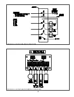
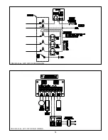
A 120V LWCO may be wired to break 120V power to the boiler (Figure 10.4a)
•
A 24V LWCO may be wired so that its contacts are wired to the external limit connections on the boiler. When
this is done a separate transformer must be supplied by the installer to power the LWCO’s sensing circuit. This
transformer must be completely isolated from the boiler wiring (Fig 10.4b).
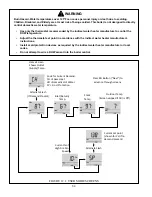
CAUTION
When making low voltage connections, make sure that no external power source is
present in the thermostat or limit circuits. If such a power source is present, it could
destroy the boiler’s control. One example of an external power source that could be
inadvertently connected to the low voltage connections is a transformer in the old
thermostat wiring.
Содержание GHE Series
Страница 10: ...9 Figure 5 1 Wall Layout Mounting Hole Location...
Страница 11: ...10 Figure 5 2 Boiler Mounting Bracket Installation Boiler Wall Mounting...
Страница 17: ...16 FIGURE 7 4 WALL PENETRATION CLEARANCES FOR PVC VENT PIPE...
Страница 34: ...33 FIGURE 7 24 INSTALLATION OF IPEX AND DIVERSITECH CONCENTRIC TERMINAL THROUGH ROOF...
Страница 41: ...40 FIGURE 9 2 NEAR BOILER PIPING HEATING ONLY BOILER LOOP PIPING SHOWN SHADED...
Страница 42: ...41 FIGURE 9 3a NEAR BOILER PIPING HEATING PLUS INDIRECT WATER HEATER...
Страница 43: ...42 FIGURE 9 3b NEAR BOILER PIPING HEATING PLUS INDIRECT WATER HEATER...
Страница 47: ...46 This page is intentionally left blank...
Страница 50: ...49 FIGURE 10 2 LINE VOLTAGE FIELD CONNECTIONS FIGURE 10 3 LOW VOLTAGE PCB TERMINAL CONNECTIONS...
Страница 52: ...51 FIGURE 10 4a 120V LWCO FIELD WIRING FIGURE 10 4b 24V LWCO FIELD WIRING...
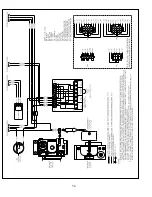
Страница 54: ...53 FIGURE 10 6 INTERNAL WIRING CONNECTIONS DIAGRAM...
Страница 55: ...54...
Страница 62: ...61 Lighting and Operating Instructions...
Страница 82: ...81 FIGURE 14 6 CONTROLS LOCATION FIGURE 14 7 PRESSURE SWITCH TUBING CONNECTIONS...
Страница 87: ...86 Blower Gas Valve Assembly for 150 180...
Страница 90: ...89...
Страница 103: ...102...
Страница 104: ...106914 02 8 16 New Yorker Boiler Co Inc P O Box 10 Hatfield PA 19440 0010 www newyorkerboiler com...


