


38
IX System Piping
A. General System Piping Precautions
WARNING
• Failure to properly pipe boiler may result in improper operation and damage to boiler or
structure.
• Install boiler so that the gas ignition system components are protected from water (dripping,
spraying, rain, etc.) during boiler operation and service (circulator replacement, etc.).
• Oxygen contamination of boiler water will cause corrosion of iron and steel boiler
components and can lead to boiler failure. Warranty does not cover problems caused by
oxygen contamination of boiler water or scale (lime) build-up caused by frequent addition of
water.
WATER QUALITY AND BOILER WATER ADDITIVES
IMPORTANT NOTE
The heat exchanger used in this boiler is made from stainless steel coils having relatively narrow waterways.
Once filled with system water, it will be subjected to the effects of corrosion, as well as fouling from any debris
introduced from the system. Take the following precautions to minimize the chance of severe heat exchanger
damage caused by corrosion and/or overheating:
1 Flush the system before connecting the boiler - In a replacement installation, flushing the system will remove
impurities, such as sediment, solder flux, metal shavings, and traces of old boiler additives. Even if the system is
new, do not omit this step – new systems will contain flux and may even contain some of the other impurities listed
above. Flush the system completely and repeat if necessary to completely remove these contaminants. If necessary,
a cleaning agent may be used to assist in system cleaning. See Part XI (“Start-up and Check-out”) for recommended
cleaners.
2. Make sure that the system is tight - This is the single most important guideline. Tap water contains dissolved
oxygen which causes corrosion. In a tight system, this oxygen comes out of solution and is quickly removed from
the system through the automatic air vent. The system then remains essentially free of oxygen. If the system is not
tight, however, frequent additions of make-up water can expose the heat exchanger to oxygen on a continuous basis.
In addition, frequent additions of hard make-up water can cause calcium deposits to collect in the heat exchanger,
causing severe damage. To minimize additions of make-up water:
• Inspect the system thoroughly for leaks before placing it in service.
• If the system includes underground piping, or other piping in which a leak might go undetected, consider
isolating the boiler from the system with a heat exchanger.
• Make sure that the expansion tank is properly sized and in good condition. If it is not, the relief valve may
open frequently, resulting in regular additions of make-up water.
• If an automatic fill valve is installed, installation of a water meter in the fill line is strongly recommended
so that routine additions of make-up water can be detected and their cause corrected.
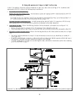
3. Non-Metallic Tubing - Even if the system is tight, oxygen can be introduced into the system through some
types of non-metallic tubing used in radiant or snow melt systems. Other nonmetallic tubing is equipped with an
oxygen barrier to prevent migration of oxygen into the water. If the boiler is to be installed in a system containing
non-metallic tubing without an oxygen barrier, it must be isolated from the boiler with a heat exchanger as shown in
Figure 9.10.
4. Water Chemistry, Antifreeze, and Boiler Water Additives – Improper boiler water chemistry can cause the heat
exchanger damage described above, as well as deterioration of seals. Observe the water chemistry requirements
shown in Part XI (“Start-up and Check-out”).
Содержание GHE Series
Страница 10: ...9 Figure 5 1 Wall Layout Mounting Hole Location...
Страница 11: ...10 Figure 5 2 Boiler Mounting Bracket Installation Boiler Wall Mounting...
Страница 17: ...16 FIGURE 7 4 WALL PENETRATION CLEARANCES FOR PVC VENT PIPE...
Страница 34: ...33 FIGURE 7 24 INSTALLATION OF IPEX AND DIVERSITECH CONCENTRIC TERMINAL THROUGH ROOF...
Страница 41: ...40 FIGURE 9 2 NEAR BOILER PIPING HEATING ONLY BOILER LOOP PIPING SHOWN SHADED...
Страница 42: ...41 FIGURE 9 3a NEAR BOILER PIPING HEATING PLUS INDIRECT WATER HEATER...
Страница 43: ...42 FIGURE 9 3b NEAR BOILER PIPING HEATING PLUS INDIRECT WATER HEATER...
Страница 47: ...46 This page is intentionally left blank...
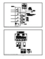
Страница 50: ...49 FIGURE 10 2 LINE VOLTAGE FIELD CONNECTIONS FIGURE 10 3 LOW VOLTAGE PCB TERMINAL CONNECTIONS...
Страница 52: ...51 FIGURE 10 4a 120V LWCO FIELD WIRING FIGURE 10 4b 24V LWCO FIELD WIRING...
Страница 54: ...53 FIGURE 10 6 INTERNAL WIRING CONNECTIONS DIAGRAM...
Страница 55: ...54...
Страница 62: ...61 Lighting and Operating Instructions...
Страница 82: ...81 FIGURE 14 6 CONTROLS LOCATION FIGURE 14 7 PRESSURE SWITCH TUBING CONNECTIONS...
Страница 87: ...86 Blower Gas Valve Assembly for 150 180...
Страница 90: ...89...
Страница 103: ...102...
Страница 104: ...106914 02 8 16 New Yorker Boiler Co Inc P O Box 10 Hatfield PA 19440 0010 www newyorkerboiler com...