


71
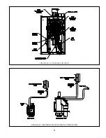
MOUNTING NUT
FLAME ROD
(FOUR PLACES)
BURNER DOOR
IGNITION
ELECTRODE
FIGURE 13.1: FLAME IONIZATION ELECTRODE AND IGNITION ELECTRODE LOCATION
j.
Unplug the ignition, ground, and flame rod wires
from the ignition electrode and the flame rod (Figure 13.1).
k.
Use a 10mm wrench to remove the four nuts
securing the fire door to the heat exchanger (Figure 13.1). Carefully
remove the door/blower/gas valve assembly from the heat exchanger, being careful not to damage the refractory
insulation on the inside of the door (see Refractory Warning on next page) or the electrodes.
l.
Inspect the heat exchanger combustion chamber and vacuum
any debris found on the coil surfaces. If necessary,
the coils may be brushed with a nonabrasive, nonmetallic brush. Do not use cleaning agents, solvents, acid or alkali
products of any type to clean the heat exchanger .
m.
Inspect the target wall and fire door insulation
. If either shows signs of damage, it must be replaced.
n.
Inspect the burner for heat damage
or other deterioration. Use a non-metallic brush or source of compressed air
to clean off dust or debris from ports.
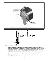
FIGURE 13.2: IGNITION ELECTRODE GAP
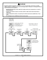
Содержание GHE Series
Страница 10: ...9 Figure 5 1 Wall Layout Mounting Hole Location...
Страница 11: ...10 Figure 5 2 Boiler Mounting Bracket Installation Boiler Wall Mounting...
Страница 17: ...16 FIGURE 7 4 WALL PENETRATION CLEARANCES FOR PVC VENT PIPE...
Страница 34: ...33 FIGURE 7 24 INSTALLATION OF IPEX AND DIVERSITECH CONCENTRIC TERMINAL THROUGH ROOF...
Страница 41: ...40 FIGURE 9 2 NEAR BOILER PIPING HEATING ONLY BOILER LOOP PIPING SHOWN SHADED...
Страница 42: ...41 FIGURE 9 3a NEAR BOILER PIPING HEATING PLUS INDIRECT WATER HEATER...
Страница 43: ...42 FIGURE 9 3b NEAR BOILER PIPING HEATING PLUS INDIRECT WATER HEATER...
Страница 47: ...46 This page is intentionally left blank...
Страница 50: ...49 FIGURE 10 2 LINE VOLTAGE FIELD CONNECTIONS FIGURE 10 3 LOW VOLTAGE PCB TERMINAL CONNECTIONS...
Страница 52: ...51 FIGURE 10 4a 120V LWCO FIELD WIRING FIGURE 10 4b 24V LWCO FIELD WIRING...
Страница 54: ...53 FIGURE 10 6 INTERNAL WIRING CONNECTIONS DIAGRAM...
Страница 55: ...54...
Страница 62: ...61 Lighting and Operating Instructions...
Страница 82: ...81 FIGURE 14 6 CONTROLS LOCATION FIGURE 14 7 PRESSURE SWITCH TUBING CONNECTIONS...
Страница 87: ...86 Blower Gas Valve Assembly for 150 180...
Страница 90: ...89...
Страница 103: ...102...
Страница 104: ...106914 02 8 16 New Yorker Boiler Co Inc P O Box 10 Hatfield PA 19440 0010 www newyorkerboiler com...