


77
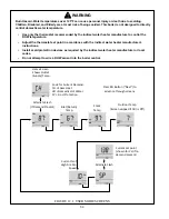
FIGURE 14.0: HOLD SCREEN
FIGURE 14.1: SUSTAINED HOLD
Outlet
(Supply)
Temp
Lockout
Code
Alternate
Flash
Lockout
FIGURE 14.2: LOCKOUT SCREEN
“Hold”
Illuminated
Outlet
(Supply)
Temp
Hold
Code
Alternate
Flash
Supply Sensor
– The boiler control infers the supply temperature based on the resistance measured at the supply sensor. Table
14.8a shows this resistance as a function of water temperature. Because the control/supply sensor is used as the boiler’s water
temperature limit control, there are actually two “thermistors” in the supply sensor wired in parallel (Figure 10.5). The control
compares the resistances across these two thermistors and prevents boiler operation if there is a significant difference between the
readings.
Return Sensor
– The boiler control infers the return temperature based on the resistance measured across a single thermistor in
the return sensor. Table 14.8a shows this resistance as a function of water temperature.
Flue Temperature Sensor
– The boiler control infers the flue gas temperature based on the resistance measured at the flue
temperature sensor. Table 14.8a shows this resistance as a function of flue temperature. There are actually two “thermistors” in
the flue temperature sensor wired in parallel (Figure 10.5). The control compares the resistances across these two thermistors and
prevents boiler operation if there is a significant difference between the readings.
Outdoor Sensor
– The boiler control infers the outdoor temperature based on the resistance measured across a single thermistor
in the outdoor sensor. Table 14.8b shows this resistance as a function of temperature.
Содержание GHE Series
Страница 10: ...9 Figure 5 1 Wall Layout Mounting Hole Location...
Страница 11: ...10 Figure 5 2 Boiler Mounting Bracket Installation Boiler Wall Mounting...
Страница 17: ...16 FIGURE 7 4 WALL PENETRATION CLEARANCES FOR PVC VENT PIPE...
Страница 34: ...33 FIGURE 7 24 INSTALLATION OF IPEX AND DIVERSITECH CONCENTRIC TERMINAL THROUGH ROOF...
Страница 41: ...40 FIGURE 9 2 NEAR BOILER PIPING HEATING ONLY BOILER LOOP PIPING SHOWN SHADED...
Страница 42: ...41 FIGURE 9 3a NEAR BOILER PIPING HEATING PLUS INDIRECT WATER HEATER...
Страница 43: ...42 FIGURE 9 3b NEAR BOILER PIPING HEATING PLUS INDIRECT WATER HEATER...
Страница 47: ...46 This page is intentionally left blank...
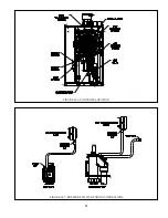
Страница 50: ...49 FIGURE 10 2 LINE VOLTAGE FIELD CONNECTIONS FIGURE 10 3 LOW VOLTAGE PCB TERMINAL CONNECTIONS...
Страница 52: ...51 FIGURE 10 4a 120V LWCO FIELD WIRING FIGURE 10 4b 24V LWCO FIELD WIRING...
Страница 54: ...53 FIGURE 10 6 INTERNAL WIRING CONNECTIONS DIAGRAM...
Страница 55: ...54...
Страница 62: ...61 Lighting and Operating Instructions...
Страница 82: ...81 FIGURE 14 6 CONTROLS LOCATION FIGURE 14 7 PRESSURE SWITCH TUBING CONNECTIONS...
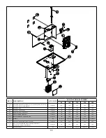
Страница 87: ...86 Blower Gas Valve Assembly for 150 180...
Страница 90: ...89...
Страница 103: ...102...
Страница 104: ...106914 02 8 16 New Yorker Boiler Co Inc P O Box 10 Hatfield PA 19440 0010 www newyorkerboiler com...


