


37
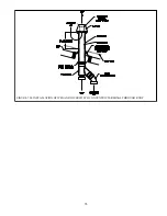
CAUTION
• Support the weight of the gas line piping independently from the boiler gas connection
fitting located on the bottom of the boiler.
• If an additional regulator is used to reduce boiler inlet pressure below 1/2 psig (3.4 kPa) it
must be at least 6 to 10 feet upstream of the boiler.
• It is very important that the gas line is properly purged by the gas supplier or utility
company.
FIGURE 8.1: GAS CONNECTION TO BOILER
TABLE 8.2: MINIMUM AND MAXIMUM INLET PRESSURES
MODEL
MAX (NATURAL & LP)
MIN (NATURAL)
MIN (LP)
80MBH
14.0”
2.5”
11.0”
100MBH
14.0”
2.5”
11.0”
120MBH
14.0”
2.5”
11.0”
150MBH
14.0”
2.5”
11.0”
180MBH
14.0”
2.5”
11.0”
NOTICE
Install 1/2” ground joint union (nut side down) as shown in Figure 8.1. Failure to do so will make it
difficult or impossible to remove burner for servicing.
Содержание GHE Series
Страница 10: ...9 Figure 5 1 Wall Layout Mounting Hole Location...
Страница 11: ...10 Figure 5 2 Boiler Mounting Bracket Installation Boiler Wall Mounting...
Страница 17: ...16 FIGURE 7 4 WALL PENETRATION CLEARANCES FOR PVC VENT PIPE...
Страница 34: ...33 FIGURE 7 24 INSTALLATION OF IPEX AND DIVERSITECH CONCENTRIC TERMINAL THROUGH ROOF...
Страница 41: ...40 FIGURE 9 2 NEAR BOILER PIPING HEATING ONLY BOILER LOOP PIPING SHOWN SHADED...
Страница 42: ...41 FIGURE 9 3a NEAR BOILER PIPING HEATING PLUS INDIRECT WATER HEATER...
Страница 43: ...42 FIGURE 9 3b NEAR BOILER PIPING HEATING PLUS INDIRECT WATER HEATER...
Страница 47: ...46 This page is intentionally left blank...
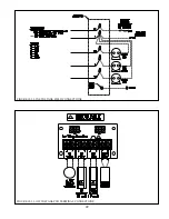
Страница 50: ...49 FIGURE 10 2 LINE VOLTAGE FIELD CONNECTIONS FIGURE 10 3 LOW VOLTAGE PCB TERMINAL CONNECTIONS...
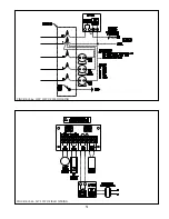
Страница 52: ...51 FIGURE 10 4a 120V LWCO FIELD WIRING FIGURE 10 4b 24V LWCO FIELD WIRING...
Страница 54: ...53 FIGURE 10 6 INTERNAL WIRING CONNECTIONS DIAGRAM...
Страница 55: ...54...
Страница 62: ...61 Lighting and Operating Instructions...
Страница 82: ...81 FIGURE 14 6 CONTROLS LOCATION FIGURE 14 7 PRESSURE SWITCH TUBING CONNECTIONS...
Страница 87: ...86 Blower Gas Valve Assembly for 150 180...
Страница 90: ...89...
Страница 103: ...102...
Страница 104: ...106914 02 8 16 New Yorker Boiler Co Inc P O Box 10 Hatfield PA 19440 0010 www newyorkerboiler com...