


11
VII Venting
A. General Vent System Design
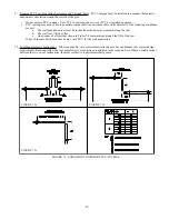
There are three basic ways to vent this boiler:
•
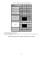
Horizontal (“Side Wall”) Twin Pipe Venting (Figure 7.0a)
- Vent system exits the building through an outside wall.
Combustion air and flue gas are routed between the boiler and the terminal(s) using separate pipes. A summary of
Horizontal Twin Pipe venting options is shown in Table 7.5.
•
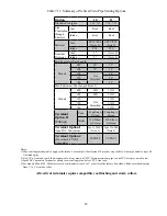
Vertical Twin Pipe Venting (Figure 7.0b)
- Vent system exits the building through a roof. Combustion air and flue gas
are routed between the boiler and the terminal(s) using separate pipes. A summary of Vertical Twin Pipe venting options
is shown in Table 7.11
•
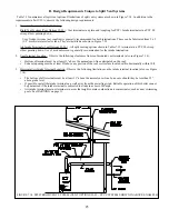
Split Venting (Figure 7.0c)
- Exhaust system exits the building through a roof, and combustion air is drawn from a
terminal mounted on the side wall. A summary of split venting options is shown in Table 7.15
WARNING
• Asphyxiation Hazard. Failure to vent this boiler in accordance with these instructions could cause
products of combustion to enter the building resulting in severe property damage, personal injury
or death.
• Do not interchange vent systems or materials unless otherwise specified.
• The use of thermal insulation covering vent pipe and fittings is prohibited.
• Do not use a barometric damper, draft hood or vent damper with this boiler.
• When using the CPVC/PVC vent option, the use of CPVC is required when venting in vertical or
horizontal chase ways.
• Any CPVC vent materials supplied with this boiler do not comply with B149.1.S1-07 and are not
approved for use in Canadian jurisdictions that require vent systems be listed to ULC S636-2008. In
these jurisdictions, vent this boiler using a listed ULC S636 Class IIB venting system.
• Do not locate vent termination where exposed to prevailing winds. Moisture and ice may form on
surface around vent termination. To prevent deterioration, surface must be in good repair (sealed,
painted, etc.).
• Do not locate air intake termination where chlorines, chlorofluorocarbons (CFC’s), petroleum
distillates, detergents, volatile vapors or other chemicals are present. Severe boiler corrosion and
failure will result.
• The use of cellular core PVC (ASTM F891), cellular core CPVC or Radel (polyphenolsulfone) is
prohibited.
• Do not locate vent termination under a deck.
• Do not reduce specified diameters of vent and combustion air piping.
• Do not allow low spots in the vent where condensate may pool.
NOTICE
This manual covers installation of vent options employing CPVC/PVC vent systems only. Other vent
options exist for this boiler which use listed polypropylene (PP) vent systems offered by several
manufacturers. Supplemental instructions for the design and installation of these vent systems with
this boiler are available on our web site.
Содержание GHE Series
Страница 10: ...9 Figure 5 1 Wall Layout Mounting Hole Location...
Страница 11: ...10 Figure 5 2 Boiler Mounting Bracket Installation Boiler Wall Mounting...
Страница 17: ...16 FIGURE 7 4 WALL PENETRATION CLEARANCES FOR PVC VENT PIPE...
Страница 34: ...33 FIGURE 7 24 INSTALLATION OF IPEX AND DIVERSITECH CONCENTRIC TERMINAL THROUGH ROOF...
Страница 41: ...40 FIGURE 9 2 NEAR BOILER PIPING HEATING ONLY BOILER LOOP PIPING SHOWN SHADED...
Страница 42: ...41 FIGURE 9 3a NEAR BOILER PIPING HEATING PLUS INDIRECT WATER HEATER...
Страница 43: ...42 FIGURE 9 3b NEAR BOILER PIPING HEATING PLUS INDIRECT WATER HEATER...
Страница 47: ...46 This page is intentionally left blank...
Страница 50: ...49 FIGURE 10 2 LINE VOLTAGE FIELD CONNECTIONS FIGURE 10 3 LOW VOLTAGE PCB TERMINAL CONNECTIONS...
Страница 52: ...51 FIGURE 10 4a 120V LWCO FIELD WIRING FIGURE 10 4b 24V LWCO FIELD WIRING...
Страница 54: ...53 FIGURE 10 6 INTERNAL WIRING CONNECTIONS DIAGRAM...
Страница 55: ...54...
Страница 62: ...61 Lighting and Operating Instructions...
Страница 82: ...81 FIGURE 14 6 CONTROLS LOCATION FIGURE 14 7 PRESSURE SWITCH TUBING CONNECTIONS...
Страница 87: ...86 Blower Gas Valve Assembly for 150 180...
Страница 90: ...89...
Страница 103: ...102...
Страница 104: ...106914 02 8 16 New Yorker Boiler Co Inc P O Box 10 Hatfield PA 19440 0010 www newyorkerboiler com...