New Rock Technologies MX100-AG Скачать руководство пользователя страница 16

Shanghai New Rock Technologies, Inc.                                                     

Page 16/23 

2.5.3 

MX120 Series 

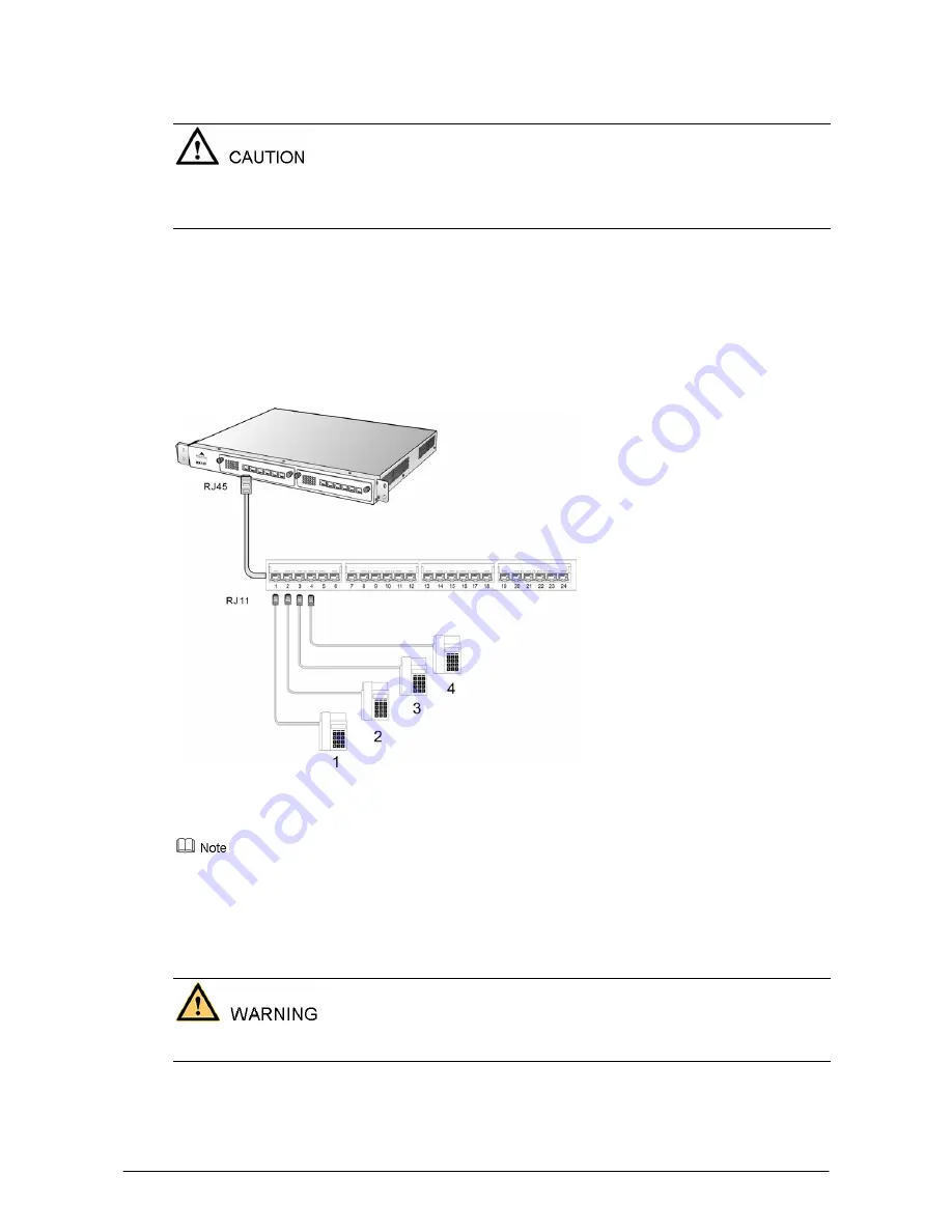
The FXS interface connects with the analog telephones via a 4-pair CAT-5 cable has RJ45 plus at 
gateway side and RJ11 plug at phone side. 


When connecting FXS or FXO interface cable, identity the interface type in each port of the interface 
card, be sure to match the line type at far end to port at equipment side. 
Insertion and extraction of the interface card must be done under the condition of power off. 

The connection steps of the FXS interface cable are as follows: 

Step 1

  Prepare the CAT-5 cable in proper length with RJ45 plug at one end. 

Step 2

  Insert the RJ45 plug of the cable into the RJ45 socket corresponding to the FXS port in the MX120 

interface card. Attach wire pairs at the other end of the cable to the patch panel in correct color coding 
order. 

Step 3

  Through the interconnection of the patch panel, the other end of the FXS interface connects with the 

telephones, fax machines or other equipments. 

Figure 2-9 FXS Interface Cable Connecting MX120 Series 


Please refer to the appendix: Standard Table for Leading Wire of MX120 RJ45 Socket Port Pin, and 
Correspondence Table for MX120 RJ45 Socket and Line Number. 

:


A standard telephone line with RJ11 plug can be inserted into the RJ45 socket. In this case, the telephone 
is attached to third line of the RJ45 port, and can be used for call testing. 

2.6 

Connecting the FXO Cable of MX8 or MX51 Series 

FXO interface cable is used to connect with the extension line of PBX or PSTN line. 


When connecting FXS or FXO interface cable, identity the interface type in each port of the interface 
card, be sure to match the line type at far end to port at equipment side. 

RJ11 connection line is used for both MX8 and MX51 to connect with the FXO interface as follows:   

Step 1

  Prepare a two-wire telephone line with RJ11 connectors at each end. 

Содержание MX100-AG

Страница 1: ...MX Voice Gateway Series Installation Manual...

Страница 2: ...Shanghai New Rock Technologies Inc Page 2 23 Revision Record Revision version 1 0 2009 05 07 Author ZNH The first revision...

Страница 3: ...l MX8 on the Workbench 12 2 2 2 Install MX51 MX100 AG and MX120 on the Workbench 12 2 3 Rack Mounting 12 2 3 1 Attaching the Brackets 12 2 3 2 Mounting the Gateway 13 2 3 3 Installation of MX120 Serie...

Страница 4: ...anghai New Rock Technologies Inc Page 4 23 4 1 Wiring Scheme for MX100 AG CHAMP Connectors 21 4 2 Wiring Scheme for MX120 Gateway 22 4 3 Standard Table for Lead Wire of Pin at Configuration Port CON 2...

Страница 5: ...o Rack 13 Figure 2 5 Front Panel of Double chassis System of MX120 Series 14 Figure 2 6 Back Panel of Double chassis System of MX120 Series 14 Figure 2 7 Connect to the FXS interface of MX8 and MX51 S...

Страница 6: ...able 1 6 Standard Configuration of MX120 10 Table 2 1 Composition of Double chassis System of MX120 Series 13 Table 2 2 Definition on Numbers of Interface Slots of MX120 System 14 Table 4 1 Wiring Sch...

Страница 7: ...d be prepared 1 1 2 Tools and Meters The tools and meters listed in table 1 1 are required for the installation Table 1 1 Tools and Meters for the Project Items Philips Screwdriver Slotted Screwdriver...

Страница 8: ...or 220V 100V 240V 47Hz 63Hz 50W MX100 AG 110V or 220V 100V 240V 47Hz 63Hz 75W MX120 Main Chassis 110V or 220V 100V 240V 47Hz 63Hz 75W MX120 Expansion Chassis 110V or 220V 100V 240V 47Hz 63Hz 50W MX8...

Страница 9: ...ter switch cable wiring and etc and make sure they are ready for the gateway AC Power Outlets The gateway needs AC power supply and sometimes the power is provided through a power strip with extension...

Страница 10: ...C250V 10A 1 Single or 2 Duplex Set Rack Mounting Kits Set 1 Single or 2 Duplex Set The packaging list in this document is only for reference Changes may be made without notification The detailed inclu...

Страница 11: ...es that need installing on the workbench the installation flow is shown in the Figure 2 1 Figure 2 1 Installation Flowchart on the Workbench 2 1 2 Installation Flowchart in the Cabinet For MX51 MX100...

Страница 12: ...ipment on the middle of the workbench 2 3 Rack Mounting The MX51 MX100 AG and MX120 series chassis are designed to be mounted on a standard 19 inch rack with 1U height 2 3 1 Attaching the Brackets Pla...

Страница 13: ...gateway is in level position and securely fixed as shown in Figure 2 4 Figure 2 4 Mount MX100 AG to Rack The gateway chassis is securely attached to the rack by the rack mounting brackets and the sup...

Страница 14: ...sion plans should reserve a position for the expansion chassis in installing a single chassis originally 2 4 Connecting the Ethernet Cable Connect one end of the Ethernet cable to the Ethernet port of...

Страница 15: ...ble identity the interface type in each port of the interface card be sure to match the line type at far end to port at equipment side Insertion and extraction of the interface card must be done under...

Страница 16: ...r Step 3 Through the interconnection of the patch panel the other end of the FXS interface connects with the telephones fax machines or other equipments Figure 2 9 FXS Interface Cable Connecting MX120...

Страница 17: ...ects with the telephones fax machines or the trunk lines of PBX The other end of the FXO interface connects with the extension lines of PBX or the PSTN lines Figure 2 10 FXS FXO Interface Cable Connec...

Страница 18: ...rotective earth contact and the earth contact of the AC power source is proper grounded Please contact the gateway supplier if the power LED does not light up after the power is turned on Never instal...

Страница 19: ...Shanghai New Rock Technologies Inc Page 19 23...

Страница 20: ...ble z Check whther the Ethernet cable the FXS and FXO cables are connected properly z Check whether the grouding cable is connected properly z Check whether the power cord is connected to the proper p...

Страница 21: ...XO FXO FXS 7 Red 32 Orange 7 FXS FXO FXO FXS 8 Red 33 Green 8 FXS FXO FXO FXS 9 Red 34 Brown 9 FXS FXO FXS FXS 10 Red 35 Gray 10 FXS FXO FXS FXS 11 Black 36 Blue 11 FXS FXO FXS FXS 12 Black 37 Orange...

Страница 22: ...eaded out and their correspondence relation is shown as the table below Category 5 cable is used for connecting interface card port and the patch panel frame Standard RJ11 telephone line may be insert...

Страница 23: ...with m in these interfaces will be bypassed to FXO line numbered with m 12 and so the terminal devices attached to FXS lines will be connected to matching external lines attach to FXO ports z Accordi...

Отзывы: