background image

Installation 

26

ProSAFE Dual Band Wireless AC Access Point Model WAC740 

Note:

Although the product package includes four wall anchors and screws, 
two screws are sufficient to attach the wall-mounting bracket as shown 
in the previous figure. However, if you prefer, you can use four screws 
and insert them through the mounting holes in the corners of the 
wall-mounting bracket.

6. 

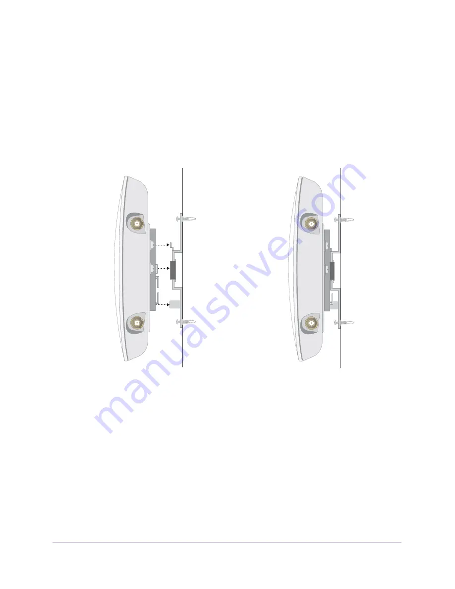
Align the three holes on the access point bracket with the three hooks on the wall-mounting 

bracket and slide the access point down until it click-attaches to the wall-mounting bracket 
and is secured. 

The following figures show a side view of the wall.

Before click-
attachment

After click-

attachment

Содержание prosafe WAC740

Страница 1: ...350 East Plumeria Drive San Jose CA 95134 USA September 2016 202 11705 01 ProSAFE Dual Band Wireless AC Access Point Model WAC740 Hardware Installation Guide...

Страница 2: ...ty For the current EU Declaration of Conformity visit http kb netgear com app answers detail a_id 11621 Compliance For regulatory compliance information visit http www netgear com about regulatory See...

Страница 3: ...HCP Server Connect the Access Point to a Computer 17 Step 3b Connect the Access Point to a Switch 18 Step 3c Provide Power to the Access Point 19 Step 4 Use the Wireless Controller to Discover and Con...

Страница 4: ...u Cannot Access the Internet From a WiFi Device 31 You Cannot Access the Access Point From a Browser 31 Test the LAN Path to the Access Point Using the Ping Utility 32 Appendix B Supplemental Informat...

Страница 5: ...tallation guide and the ceiling and wall installation guide that came with the access point and that you can download by visiting downloadcenter netgear com The chapter includes the following sections...

Страница 6: ...ps even if a 2 5 Gbps capable switch is not present on the other end Note Because model WAC740 is not intended as a standalone access point NETGEAR does not provide a separate user manual for this acc...

Страница 7: ...panel Table 1 Top panel LEDs Item Icon LED Name LED Behavior Description 1 Power LED Off Power is off Solid green Power is on and the access point is ready for operation Alternating green and amber Th...

Страница 8: ...ed and the LAG link on LAN port 1 is carrying all traffic in the LAG 4 LAN LED 2 Off No Ethernet LAG link is detected Note LAN port 2 can be used only for a LAG connection Solid green in a LAG A 1 Gbp...

Страница 9: ...rt with Auto Uplink Auto MDI X for a static link aggregation group LAG connection to a switch 5 LAN port 1 100 1000 2500BASE T Gigabit Ethernet RJ 45 port with Auto Uplink Auto MDI X and support for I...

Страница 10: ...e the following documents which you can download by visiting downloadcenter netgear com NETGEAR ProSAFE Dual Band Wireless AC Access Point WAC740 Installation Guide NETGEAR ProSAFE Dual Band Wireless...

Страница 11: ...igabit Ethernet Throughput This chapter describes the access point s connections for multi Gigabit Ethernet throughput The chapter includes the following sections Connection to a High Speed Switch Sta...

Страница 12: ...the access point To connect the access point to the switch you must use access point LAN port 1 the rightmost LAN port All ports on the NETGEAR M4200 ProSAFE Managed Switch support at least 2 5 Gbps a...

Страница 13: ...ou set up a static LAG the access point s 2 5 Gbps Ethernet port LAN port 1 is limited to 1 Gbps and the total throughput of the LAG connection is 2 Gbps LAN port 1 provides 1 Gbps and LAN port 2 prov...

Страница 14: ...sider the WiFi Equipment Placement and Range Guidelines Step 3 Connect the Access Point to Your Network Step 4 Use the Wireless Controller to Discover and Configure the Access Point Step 5 Test WiFi C...

Страница 15: ...t Placement and Range Guidelines The range of your WiFi connection can vary significantly based on the location of the access point The latency data throughput performance and power consumption of WiF...

Страница 16: ...tuation you must use a computer to connect to the access point so that you can configure the network IP address of the access point see Step 3a If the Network Does Not Include a DHCP Server Connect th...

Страница 17: ...t LAN port 1 on the access point to an Ethernet port on your computer 3 In the address bar of a web browser enter the IP address of the access point The default IP address is 192 168 0 160 A login win...

Страница 18: ...s type of setup see Static LAG Connection to a Switch on page 13 To set up a LAG between the access point and the switch 1 Connect one end of a Category 5e Cat 5e cable included with the access point...

Страница 19: ...he PoE Ethernet connection to the switch controls the power Option 2 Connect the Access Point to a Power Adapter If your switch does not provide PoE obtain a 12 VDC 2 5A power adapter from NETGEAR Thi...

Страница 20: ...to reduce interference The recommended channel spacing between adjacent access points is five channels for example use Channels 1 and 6 or 6 and 11 or 1 and 11 Step 5 Test WiFi Connectivity to the Ac...

Страница 21: ...and Wall Installation Kit Figure 6 Ceiling and wall installation kit The ceiling and wall installation kit contains the following components 1 One access point mounting bracket 2 One wall mounting bra...

Страница 22: ...and test the access point to verify WiFi network connectivity If you are mounting the access point on a hard ceiling use the wall installation instructions Note Do not place the access point in a fal...

Страница 23: ...oint Model WAC740 2 Place the access point so that the ceiling rail is between the two tabs on the access point mounting bracket 3 Twist the access point to hang it from the ceiling rail 4 Secure the...

Страница 24: ...where you want to mount the access point 2 Mark the wall where the two mounting holes are see the figure in Step 5 3 Attach the access point mounting bracket to the access point using the four mounti...

Страница 25: ...wall anchors and screws attach the wall mounting bracket to the wall where you previously marked The following figures show a side view of the wall The left figure includes a schematic view of the wa...

Страница 26: ...re However if you prefer you can use four screws and insert them through the mounting holes in the corners of the wall mounting bracket 6 Align the three holes on the access point bracket with the thr...

Страница 27: ...Access Point From a Browser Test the LAN Path to the Access Point Using the Ping Utility IMPORTANT For information about access point discovery or connection problems with the wireless controller and...

Страница 28: ...int is receiving insufficient PoE power Make sure that PoE switch is not overloaded If you connected the access point to a PoE 802 3af switch disconnect it and connect it to a PoE 802 3at switch inste...

Страница 29: ...cted If any of these conditions does not occur see the appropriate following section The Power LED Remains Solid Amber or Remains Blinking Amber When the access point starts while it is controller man...

Страница 30: ...nto a working power outlet or power strip Make sure that the PoE switch is functioning normally If you use a power cord to provide power to the access point check these items Make sure that the power...

Страница 31: ...ce These settings must be the same as the settings that are configured on the access point Ping the IP address of the access point to verify that a WiFi connection exists between the WiFi enabled comp...

Страница 32: ...r tab or your changes are lost Click the Refresh or Reload button in the web browser It is possible that the changes occurred but the web browser is caching the old configuration Test the LAN Path to...

Страница 33: ...are off follow the instructions in The Activity LED LAN LED 1 or Both LAN LEDs Are Not Lit on page 30 Check to see that the corresponding link LEDs are lit for your network interface card and for the...

Страница 34: ...is appendix provides factory default settings and technical specifications for the ProSAFE Dual Band Wireless AC Access Point Model WAC740 The appendix includes the following sections Technical Specif...

Страница 35: ...settings Wireless controller IP address Management VLAN settings Link aggregation settings Hardware interfaces 1 LAN 100 1000 2500BASE T Gigabit Ethernet RJ 45 PoE port 1 LAN 10 100 1000BASE T Gigabi...

Страница 36: ...off and light again Environmental specifications Operating temperature 0 to 40 C 32 to 104 F Operating humidity 10 90 noncondensing Electromagnetic compliance FCC Part 15 SubPart B FCC Part 15 SubPar...

Отзывы: