background image

Installing the RF Antenna

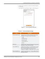
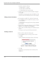
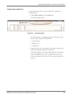
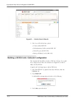
This section contains the instructions for the RF antenna installation.

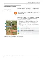
Locating the Site

Choose a location that does not interfere with any other wiring and
is easily accessible.

The first step in securing the R450 DC pole in the ground is to locate
where the RF 450 MHz antenna will be seated. Complete these
instructions to locate the site for the pole.

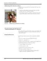
1. Locate the conduit for the RF 450 MHz antenna cable and the

trench where the cable for the RF 450 MHz antenna will be
buried.

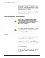
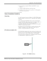
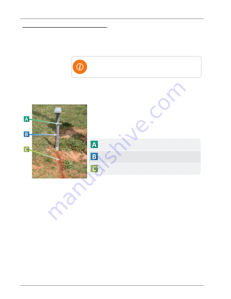
2. Find a suitable spot close in this location to seat the RF antenna.

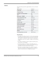
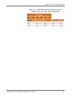
See Figure 73.

RF 450 MHz antenna cable

RF 450 MHz antenna protective conduit

RF 450 MHz antenna cable trench

Figure 73  – RF 450 MHz Antenna Cable and Trench

R450 Data Collector Installation and Maintenance Guide

99

Appendix A: RF Antenna Installation

Содержание R450

Страница 1: ...R450 Data Collector Installation and Maintenance Guide R450 Data Collector Installation and Maintenance Guide ...

Страница 2: ......

Страница 3: ...R450 Data Collector Installation and Maintenance Guide ...

Страница 4: ... interference received including interference that may cause undesired operation NOTE This equipment has been tested and found to comply with the limits for a Class A digital device pursuant to Part 15 of the FCC Rules These limits are designed to provide reasonable protection against harmful interference in a residential installation This equipment generates uses and can radiate radio frequency e...

Страница 5: ...pliance could void the user s authority to operate the equipment Industry Canada This Class A digital apparatus meets all requirements of the Canadian Interference Causing Equipment Regulations Operation is subject to the following two conditions 1 this device may not cause harmful interference and 2 this device must accept any interference received including interference that may cause undesired ...

Страница 6: ... is not intended to be powered directly from the Mains Distribution System Mesures de sécurité importantes Examinez les mesures de précaution suivantes avant l installation Examinez les mesures de précaution suivantes avant l installation Les raccordements au secteur alternatif doivent être effectués par un électricien qualifié Aucune pièce ne peut être installée par l utilisateur à l intérieur L ...

Страница 7: ...napproprié Disposez des batteries usagées conformément aux instructions du fabricant Double Pole Neutral Fusing Fusible bipolaire neutre R450 Data Collector Installation and Maintenance Guide Literature No IM R450 Data Collector 05 2020 Part No 12835 001 Neptune Technology Group Inc 1600 Alabama Highway 229 Tallassee AL 36078 Tel 800 633 8754 Fax 334 283 7293 Copyright 2003 2020 Neptune Technology...

Страница 8: ...This page intentionally left blank ...

Страница 9: ... the R450 System 8 R450 DC Kits 8 GPRS Modem 8 Wi Fi Modem 9 Ethernet 9 CDMA Modem 10 Chapter 2 General Installation Guidelines 11 R450 DC Specifications 11 Electrical Specifications 11 Environmental Conditions 11 Mechanical Specifications 11 R450 DC Footprint 11 Safety Approval 11 Storage 12 Unpacking 12 R450 DC Installation Kits 12 Tools and Materials 13 R450 MIU and Magnet 14 Chapter 3 Installa...

Страница 10: ...e Power 28 Completing the Installation 29 Testing the Connections 29 Swiping the MIU 30 If No Email is Received 31 Manually Configuring the GPRS Modem 32 Required Equipment 32 Configuring the GPRS Modem 33 Securing the R450 DC 33 Installing a Wall Mount System 34 Mounting the R450 DC to a Wall 35 35 Connecting the Cables to the R450 DC 36 Mounting the Antennas and Antenna Mast 36 Mounting the Ante...

Страница 11: ...49 Unpacking and Inspection Checklist 52 Save the Shipping Container 52 Read This Manual 52 The Novus Micro Secure 53 Site Preparation Checklist 55 Grounding 55 Branch Circuit Breaker Protection 55 Disconnects 56 Site Requirements 56 Mounting the UPS 57 Wall Mounting 57 Pole Mounting 57 Steel or Concrete Pole Mounting 57 Wooden Pole Mounting 58 Connecting the UPS 58 Tools and Materials Required 58...

Страница 12: ...ems 70 Chapter 6 Troubleshooting 73 Equipment Required 73 PC Notebook Configuration 74 Additional Equipment Required for the Computer 74 Potential R450 DC Problems 74 Multiple R450 DCs Not Syncing with Host Database 74 Storm Damage Affecting Multiple Sites 75 First Steps 75 Initial Site Activities 75 Checking the General Health of Each of the Modules 76 Visual Check of CPU Board Power 76 Visual Ch...

Страница 13: ...81 Transmitter Transmits but ALM Indicator Flashes 82 Measuring the VSWR 82 The Radio Never Transmits 83 Reduction in Amount of Data Collected 83 Contacting Customer Support 84 By Phone 84 By Email 84 Appendix A RF Antenna Installation 85 RF Antenna Overview 85 Mounting the Antennas 85 Site Recommendations 85 Feed Line and Antenna Recommendations 86 Feed Line 86 Feed Line Requirements 86 Neptune P...

Страница 14: ...bleshooting the RF Antenna 102 Equipment Required 102 Appendix B Flash Drive Configuration for R450 DC 105 Overview 105 Creating a Collector 105 Creating a New Collector 105 Editing Collector Information 108 Deleting a Collector 108 Using Collector Search 109 Building a USB Drive for Collector Configuration 110 Appendix C Ethernet Termination 111 Straight Through Ethernet Cable 111 RJ 45 Crossover...

Страница 15: ... 15 Antenna Connections 19 Figure 16 Ground Wire 20 Figure 17 Items for GPRS or Wi Fi Antenna 20 Figure 18 Attaching the GPRS or Wi Fi Antenna 21 Figure 19 Tighten Bolt for GPRS Antenna 21 Figure 20 Cable to GPRS Antenna 22 Figure 21 GPRS Antenna Connection at Base 22 Figure 22 Weatherizing Connections 23 Figure 23 Weatherizing the Base Connection 23 Figure 24 Weatherizing the Antenna Connection 2...

Страница 16: ...e 45 RJ45 Ethernet Housing 41 Figure 46 Connecting the R450 DC 42 Figure 47 Novus Micro Secure Cable Version 53 Figure 48 Novus Micro Secure Surveillance Version 53 Figure 49 Output Connectors and Monitoring LEDs 54 Figure 50 Wall Mounting 57 Figure 51 Steel or Concrete Pole Mounting 57 Figure 52 Wooden Pole Mounting 58 Figure 53 Wire Input and Output Connectors 59 Figure 54 Battery Locations 60 F...

Страница 17: ...ns 79 Figure 71 CalAmp Modem with RSSI LED 80 Figure 72 RF 450 MHz Antenna 97 Figure 73 RF 450 MHz Antenna Cable and Trench 99 Figure 74 RF 450 MHz Antenna to be Mounted 100 Figure 75 RF 450 MHz Antenna Connection 101 Figure 76 Antenna Connections 101 Figure 77 Weatherizing the RF Antenna Connection 102 Figure 78 Create a New Collector Window 105 Figure 79 Collector Network Setting Tab 107 Figure ...

Страница 18: ...This page intentionally left blank xvi R450 Data Collector Installation and Maintenance Guide Tables ...

Страница 19: ... de l ASI 47 Table 10 Battery Safety Checklist 50 Table 11 UPS LED Descriptions 62 Table 12 UPS Troubleshooting 62 Table 13 Neptune Part Numbers for Cable and Connectors 87 Table 14 Connectors and Accessories 88 Table 15 Power Measurement to Return Loss and VSWR Conversion Table Part I 90 Table 16 Power Measurement to Return Loss and VSWR Conversion Table Part II 91 Table 17 Coax Cable Loss Table ...

Страница 20: ...This page intentionally left blank xviii R450 Data Collector Installation and Maintenance Guide Tables ...

Страница 21: ...oduct Overview This section provides a general description of the R450 Data Collector R450 DC Model 450C The R450 DC receives stores and communicates meter reading data to the host software N_SIGHT PLUS in the host computer The R450 DC collects meter reading data from Neptune s R450 Meter Interface Unit MIU interfacing with Neptune s absolute encoder register This data can later be uploaded to the...

Страница 22: ...ons There are four R450 DC variants depending on the backhaul communications required Each type is powered by single phase AC main power 120V 60 Hz Neptune provides an installation kit for each type of installation The standard configuration of the R450 DC backhaul is a General Packet Radio Service GPRS modem Other available backhaul options include using an Ethernet connection a Wireless Fidelity...

Страница 23: ...RTISSEMENT N installez pas l enregistreur de données R450 DC le mât d antenne ou l antenne d un poteau ou d une structure semblable amenant un éclairage électrique ouvert des fils électriques ou des fils de prise de courant de plus de 250 volts Voir l article 810 du N E C Figure 2 on page 3 illustrates how the R450 DC can be installed Figure 2 Site Selection R450 Data Collector Installation and Ma...

Страница 24: ...nents for the R450 DC Wall Mount A wall mounted R450 DC can be installed indoors however because the unit uses an external antenna an antenna mast is needed Refer to Figure 3 for how to mount the R450 DC to a wall Figure 3 Wall Mount Installation Depending upon the availability of communications GPRS Wi Fi Ethernet or CDMA modems can be used 4 R450 Data Collector Installation and Maintenance Guide...

Страница 25: ... Wi Fi Ethernet or CDMA modems can be used Pole Installation The pole installation is used for an outdoor free standing pole Refer to Figure 5 for how to install the R450 DC on a pole Figure 5 Pole Installation Depending upon the availability of communications GPRS Wi Fi Ethernet or CDMA modems can be used R450 Data Collector Installation and Maintenance Guide 5 Chapter 1 Product Description ...

Страница 26: ...une provides a propagation model which uses sophisticated software to predict the system performance If you place an R450 DC somewhere else it may not perform well CAUTION If Neptune s propagation model is not followed then inadequate performance can occur Owners of both licensed and unlicensed equipment are responsible for the proper operation of their equipment If it is not operating within spec...

Страница 27: ...residences and businesses can have equipment that interferes with the R450 System Site surveys often find these problems but cannot detect intermittent factory shift related or other time specific sources of interference Being in close proximity to a high power commercial broadcast antenna produces a unique set of problems Loose or badly corroded hardware on or near the site can cause signals from...

Страница 28: ...ain using the radio receiver can identify new sources of interference Problems related to specific time windows should have the surveys performed during those time periods R450 DC Kits The following section describes the components for each of the four R450 DC kits GPRS Modem The R450 DC is mounted on either a pole wall or a stand The following list includes the parts needed for the R450 DC GPRS m...

Страница 29: ...ith the R450 DC 1 12842 001 Strut clamp one inch Stainless Steel included with the R450 DC 1 N A Hardware kit bolts washers nuts included with the R450 DC Adalet M10292 1 12835 001 R450 DC Installation and Maintenance Guide 1 Table 2 Wi Fi Modem Parts List 12799 200 Ethernet The following list includes the parts needed for the R450 DC Ethernet kit Part Number Description Qty 12799 300 R450 DC AC p...

Страница 30: ...ith the R450 DC 1 12842 001 Strut clamp one inch Stainless Steel included with the R450 DC 1 N A Hardware kit bolts washers nuts included with the R450 DC Adalet M10292 1 12835 001 R450 DC Installation and Maintenance Guide 1 13163 010 Conversion Kit Assembly CalAmp CDMA modern Verizon 1 13163 010 Conversion Kit Assembly CalAmp CDMA modem Sprint 1 Table 4 CDMA Modem Parts List 12799 010 Verizon 12...

Страница 31: ...1 0A 60Hz Power Consumption 50 Watts Environmental Conditions Operating Temperature1 22 to 140 F 30 to 60 C Storage Temperature 40 to 185 F 40 to 85 C Operating Humidity 0 to 95 Non condensing Environmental Rating UL50E Type 4X Operating Altitude Less than 6561 feet 2000 meters 1 For installations that have ambient temperatures that exceed 110 F 43 3 C the R450 DC must be installed in a well venti...

Страница 32: ...parts of the R450 DC appear to be damaged or prove to be defective upon installation notify your Neptune sales representative If the unit or item requires reshipment use the original cardboard box and packing material R450 DC Installation Kits The RF 450 MHz antenna and accessories are now ordered separately from the R450 DC The RF 450 MHz antenna coax cables and coax connectors must be ordered as...

Страница 33: ...ndard box end wrench set l Hammer l Channel locks Various installation procedures performed by the installer UV Stable Ties 8 and 12 20 32 cm and 30 48 cm Securing coax cable Cable Clips Various sizes Securing coax cable R450 DC Key Key for lock on unit Securing the unit Concrete Blocks 8 x 8 x 16 20 32cm x 20 32cm x 40 64cm Ballast for the R450 DC stand Weatherizing Kit PolyPhasor P N WK 1 or Tim...

Страница 34: ...gnet with you when you install the R450 DC These items are needed to test the unit See Swiping the MIU on page 27 Be sure that the N_SIGHT R450 Host Software is running and that you have an R450 MIU and magnet with you when you install the R450 DC You will use the R450 MIU to test the unit 14 R450 Data Collector Installation and Maintenance Guide Chapter 2 General Installation Guidelines ...

Страница 35: ... Locating the Site Choose a location that does not interfere with any other wiring and is easily accessible After selecting a site complete the following procedures The first step in securing the R450 DC pole in the ground is to locate where the RF 450 MHz Antenna has been seated Complete these instructions to locate the site for the pole 1 Locate the conduit for the RF 450 MHz antenna cable and t...

Страница 36: ...le against a firm crushed stone base on firm compacted soil a minimum of 6 inches below the front line encased in reinforced concrete per ASTM standards The pole is to be level and plumb Figure 9 Pole Seated in Ground CAUTION Be sure not to dig this hole in the antenna cable trench Mounting the R450 DC to the Pole To mount the R450 DC to the pole complete the steps on following page Strut channels...

Страница 37: ...ow the top of the pole Figure 10 Assembling Strut Channels Figure 11 Mounting Hardware Stack Detail 4 Attach the box to the pole using 2 strut clamps Beginning with the top strut channel 5 Attach the top part of the unit to the top of the pole See Figure 12 6 Tighten the bolts with a wrench as illustrated in Figure 13 7 Attach the bottom part of the unit to the pole using 2 strut clamps Figure 12 ...

Страница 38: ...s Attaching Cables for the R450 DC The corresponding sections detail how to attach the following components l RF 450 MHz Antenna Cable l Ground wire l AC Power source Refer to the following sections for the steps to attach these items Figure 14 RF 450 MHz Antenna Connection 18 R450 Data Collector Installation and Maintenance Guide Chapter 3 Installation of the R450 DC ...

Страница 39: ...f the coaxial cable must be connected to earth grounded at the entrance to the building Do this in accordance with applicable national electrical installation codes Section 820 93 of the National Electrical Code ANSI NFPA 70 Soyez particulièrement attentif lorsque vous installez l enregistreur de données R450 à l intérieur d un bâtiment L enregistreur de données R450 est installé à l intérieur d u...

Страница 40: ...r 4 American Wire Gauge AWG copper wire with a minimum temperature rating of 75 C 3 Tighten with a flathead screwdriver Torque to 35 in lb 4 0 Nm Figure 16 Ground Wire Mounting the GPRS or Wi Fi Antenna To mount the GPRS or Wi Fi antenna complete the following steps 1 Locate all six of the items for the GPRS antenna illustrated in Figure 17 Figure 17 Items for GPRS or Wi Fi Antenna 20 R450 Data Co...

Страница 41: ...a only Damage can occur if any other part of the antenna is used AVERTISSEMENT Il est important de fixer la pince autour de la bande noire de l antenne GPRS ou Wi Fi uniquement Des dommages peuvent survenir si une autre partie de l antenne est utilisée 3 Using a 3 8 inch socket wrench tighten the bolt for the strut clamp around the GPRS or Wi Fi antenna with a wrench as illustrated in Figure 19 Fi...

Страница 42: ...rth grounded at the entrance to the building Do this in accordance with applicable national electrical installation codes Section 820 93 of the National Electrical Code ANSI NFPA 70 Soyez particulièrement attentif lorsque vous installez l enregistreur de données R450 à l intérieur d un bâtiment L enregistreur de données R450 est installé à l intérieur d un bâtiment L écran blindage du câble coaxia...

Страница 43: ...re 22 2 Wrap the tape around the connection several times slowly work your way downward to weatherize you connection at the base Figure 22 Weatherizing Connections 3 Repeat steps one and two to weatherize the GPRS or Wi Fi connection at the base of the R450 DC as illustrated in Figure 23 Figure 23 Weatherizing the Base Connection R450 Data Collector Installation and Maintenance Guide 23 Chapter 3 ...

Страница 44: ...se 12 AWG single insulated copper wire with a minimum temperature range of 167 F 75 C Refer to NEC table 310 17 MISE en GARDE Les connexions pour le câblage de l enregistreur de données R450 doivent être effectuées selon le tableau suivant Utilisez un fil de cuivre isolé de calibre 12 AWG calibrage américain normalisé des fils avec une plage de température minimale de 75 C 167 C Voir le tableau 31...

Страница 45: ...onnect the AC power to the R450 DC complete the following steps 1 With the key open the door to the R450 DC 2 Use a listed UL or CSA Type 4x conduit connector to thread the AC cable through the bottom of the R450 DC unit as illustrated in Figure 25 Figure 25 AC Wiring Threaded Through Base 120V AC Installation Connecting the AC Power Wires Connect the wiring for the AC power in the R450 DC by comp...

Страница 46: ...white wire line and neutral to the plastic anchor just below the breaker using a wire tie Figure 28 R450 DC Wiring Diagram 120V AC Illustration Configuring the GPRS Modem Complete the following steps to configure the GPRS modem 1 Turn the power off for the R450 DC 2 Insert SIM card in the GPRS modem 3 Connect the GPRS modem to the laptop using the Ethernet cable 4 Turn the power on for the R450 DC...

Страница 47: ...on page 55 Configuring the Collector with the USB Flash Drive Complete the following steps to configure the R450 DC with the USB flash drive 1 Configure the USB flash drive as described in USB Flash Drive Configuration for R450 Data Collection on page 87 2 Insert the USB flash drive included with R450 DC into either one of the two available USB ports on the CPU board Figure 29 USB Port on CPU Boar...

Страница 48: ...d in Figure 30 3 Close the door of the AC power box Figure 30 Main Disconnect Breaker Switch 4 Push the main breaker switch in the R450 DC up to activate power to the unit 5 Wait five minutes for the R450 DC to complete the configuration sequence 6 Remove the USB flash drive Figure 31 Power On R450 DC 28 R450 Data Collector Installation and Maintenance Guide Chapter 3 Installation of the R450 DC ...

Страница 49: ...r the audible sounds l There will be one audible beep approximately five seconds after activating the unit l A second beep should occur approximately 45 seconds after the first beep l There should be no other audible beeps after the second beep 2 Check to be sure the power light is on at the bottom of the Midland Radio See R450 DC on page 12 3 Check to see if the power light is on for the modem GP...

Страница 50: ...n D4 Green Link Integrity D5 Yellow Activity D6 Red 10 100 Table 7 Lights on the CPU Board 5 After the R450 DC has been powered up for five minutes remove the USB flash drive from the CPU board Swiping the MIU Before you can proceed with these steps the R450 DC must be set up in the N_SIGHT PLUS host software See Creating a Collector on page 87 and Building a USB Drive for Collector Configuration ...

Страница 51: ... the host software See the following example Figure 33 Email Sent from R450 DC l Make sure the email comes from the R450 DC that you are installing l If you do receive an email continue to the instructions outlined in Securing the R450 DC on page 29 l If you do not receive an email continue to the instructions outlined in If No Email is Received If No Email is Received If you do not receive an ema...

Страница 52: ...onfiguring the GPRS Modem If you have an Ethernet connection consult with your utility network IT group Your GPRS service provider will need to manually set up the GPRS modem To manually set up an account your service provider will require the necessary information username password and APN Access Point Name Refer to the setup guide included with the modem Manually Configuring the GPRS Modem To ma...

Страница 53: ...rational contact the service provider 6 On the R450 DC perform a power cycle and follow the startup procedures Securing the R450 DC After you finish the configuration complete the following steps to lock the R450 DC 1 Close the door of the R450 DC 2 Using the key that is supplied with the unit secure the bottom lock of the R450 DC as illustrated in Figure 34 Figure 34 Bottom Lock of Unit 3 Use a f...

Страница 54: ...ables to the R450 DC on page 1 3 Mounting the GPRS or Wi Fi Antenna on page 1 4 Attaching the Horizontal Crossbar on page 1 5 Attaching the Antenna on page 1 6 Mounting the Antenna Mast to the Building on page 1 7 Connecting the Cables to the R450 DC on page 1 8 Testing the Connections on page 1 Table 8 Installing a Wall Mount System 34 R450 Data Collector Installation and Maintenance Guide Chapte...

Страница 55: ...gure 36 complete the following Using the seal washers on the inside of the box secure the box to the wall in one of the following ways l If mounting to wood studs use the supplied seal washer and 3 long 3 8 inch lag bolts l If mounting to masonry use the supplied seal washer and 3 long 3 8 inch lag bolts Figure 36 R450 DC Mounted on Wall R450 Data Collector Installation and Maintenance Guide 35 Ch...

Страница 56: ... must be grounded to the same grounding electrode used for the building s electrical system to ensure that all exposed non current carrying metal parts are the same potential Refer to NEC Article 810 MISE en GARDE Le mât et le support de l antenne doivent être mis à la terre avec la même électrode de mise à la terre que celle utilisée pour le système électrique du bâtiment afin de garantir que tou...

Страница 57: ... than 250V per N E C Article 810 C E C Section 54 AVERTISSEMENT Ne montez pas d antennes sur des poteaux électriques des mâts de service électrique ou d autres structures amenant des fils électriques ou d éclairage Les câbles coaxiaux doivent garder un dégagement d au moins 2 pieds 0 61 m des fils électriques ou d éclairage de moins de 250 V ou d au moins 10 pieds 3 048 m des fils électriques de p...

Страница 58: ...e up the pole in the two brackets See 8 Secure the pole with the bolts provided Figure 39 Lining Up Second Bracket Mounting the Appropriate Communications Antenna Depending upon the type of modem you are using for communications with your R450 DC refer to the following instructions for installing the appropriate antenna Mounting the GPRS or Wi Fi Antenna This step is only for kits using a GPRS mod...

Страница 59: ...ecure one end of the crossbar to the vertical pole making sure the crossbar is perpendicular to the pole See Figure 40 Figure 40 Securing the Crossbar Attaching the Antenna After mounting the horizontal crossbar you can mount the GPRS or Wi Fi antenna To mount the GPRS or Wi Fi antenna complete the following steps 1 Locate a position on the crossbar approximately 2 inches from the end See Figure 4...

Страница 60: ... connection using the weatherizing kit 6 After the antenna is mounted it is important to secure the cable using Ultra Violet UV approved cable ties or clips as illustrated in Figure 42 Figure 42 Securing the Wiring Connecting the Ethernet Cable This step is only for kits using a Ethernet modem If you are using a GPRS or Wi Fi modem and antenna refer to Mounting the GPRS or Wi Fi Antenna on page 1 ...

Страница 61: ... Through Assembly 4 Tighten the feed through assembly to create a seal 5 Tighten the compression nut loosely 6 Screw the entire feed through assembly into the RJ45 Ethernet housing which is already mounted at the bottom of the R450 DC Refer to Figure 45 There should be a rubber gasket between the two assemblies 8 Tighten the compression nut until the gaskets are tight around the RJ45 cable Figure ...

Страница 62: ... illustrated in Figure 46 Figure 46 Connecting the R450 DC 3 Thread the cables through to the RF 450 MHz Antenna 4 Wire the AC power as described in Installation of the R450 DC on page 15 5 Weatherproof all coax cables using the weatherizing kit 6 Verify all the connections as described in Testing the Connections on page 29 42 R450 Data Collector Installation and Maintenance Guide Chapter 3 Instal...

Страница 63: ...était emballé avec l alimentation sans interruption ASI Il contient d importantes instructions d installation et d utilisation Conservez le en lieu sûr CAUTION The emergency shutdown procedure is on the inside rear cover of the Operator s Manual AVERTISSEMENT La procédure d arrêt d urgence se trouve sur la couverture arrière intérieure du Manuel de l opérateur UPS Specifications This section provi...

Страница 64: ... are rated at 120VAC 1A The factory default settings are l C1 On battery l C2 Low battery l Cable Version None Display l Surveillance version two LEDs 1 red and 1 green via communication board l Cable version two LEDs 1 red and 1 green mounted on the enclosure visible from the outside Regulatory Specifications Specification Description Electrical Safety UL 1778 CSA 22 2 107 1 EN50091 2 EN60950 Emi...

Страница 65: ...C l 0 43 230VAC Power W VA 100 total including auxiliary output Waveform Sine wave Load Crest Factor 3 1 load dependent Output Voltage Distortion 3 THD resistive load Efficiency typical backup 85 75 Transfer Time mS l AVR to Backup 5 typical l Backup to AVR 3 typical Line Qualifications Time seconds 3 Battery String Voltage VDC 24 Battery Charger Current A 3 0 Battery Charger Temperature Compensat...

Страница 66: ...ation sécuritaire d alimentations électriques à haute énergie et de leurs batteries Elles sont également censées connaître les codes électriques locaux et leur application sécuritaire DANGER Never let water from rain a hose tap or a sprinkler s output road splash or other water sources enter the UPS to prevent accidental shorts shocks or electrocutions DANGER Ne laissez jamais l eau de la pluie d ...

Страница 67: ...z soigneusement les composants Signalez immédiatement tout dommage dû au transport ou tout autre dommage en même temps Always assume electrical connections or conductors are live Turn off all circuit breakers and double check with a voltmeter before performing installation or maintenance Il faut toujours supposer que les connexions électriques ou les conducteurs sont sous tension Coupez tous les d...

Страница 68: ...ASI peut fonctionner à une température maximale de 50 C Voir également la section des spécifications pour les températures nominales At high ambient temperature conditions the UPS s surface can be very hot to the touch Dans des conditions de température ambiante élevée la surface de l ASI peut être très chaude au toucher There is a Lithium battery inside the UPS There is a danger of an explosion i...

Страница 69: ...ater MISE en GARDE Procédures d urgence concernant la batterie l Si des éclaboussures d électrolyte touchent votre peau lavez immédiatement la zone affectée avec de l eau l Si de l électrolyte entre en contact avec vos yeux lavez les pendant au moins 10 minutes sous l eau courante ou avec une solution de lavage oculaire neutralisante spéciale Consultez immédiatement un médecin l Neutralisez l élec...

Страница 70: ...d if such grounds are removed during installation and maintenance applicable to equipment and remote battery supplies not having a grounded supply circuit MISE en GARDE l L installation et l entretien de la batterie doivent être effectués ou supervisés par une personne qui connaît les batteries et les précautions requises l Remplacez toujours les batteries par le même type de batterie les mêmes ch...

Страница 71: ...jamais ouvrir ou endommager les batteries L électrolyte libéré est nocif pour la peau et les yeux Il peut être toxique et dangereux pour l environnement Never let live battery wires touch the UPS the enclosure or any other metal objects This can cause a fire or explosion Ne laissez jamais des fils de batterie sous tension toucher l ASI le boîtier ou tout autre objet métallique Cela peut provoquer ...

Страница 72: ...r Phillips head wood screws l Two or four batteries as ordered l One battery fuse Standard 30A automotive fuse l Any ordered options Save the Shipping Container To return the Micro Secure for servicing pack it in the original shipping container Alpha Technologies is not responsible for any damages caused by improper packaging of returned products Read This Manual Before installation become familia...

Страница 73: ...Novus Micro Secure Figure 47 Novus Micro Secure Cable Version For more information on the LED see Table 11 on page 62 Figure 48 Novus Micro Secure Surveillance Version R450 Data Collector Installation and Maintenance Guide 53 Chapter 4 I Uninterruptible Power Supply ...

Страница 74: ...a bar with monitoring LEDs an RS232 connector and dry contacts for attachment of an external monitoring panel Figure 49 Output Connectors and Monitoring LEDs 54 R450 Data Collector Installation and Maintenance Guide Chapter 4 I Uninterruptible Power Supply ...

Страница 75: ...inspection avant l installation pour s assurer que la mise à la terre est conforme au code local d électricité Branch Circuit Breaker Protection CAUTION To provide branch circuit protection the utility line attached to the UPS s input must be protected by a circuit breaker certified for this use as per the local electrical code The breaker s minimum size is calculated by the following formula Mini...

Страница 76: ...AUTION The input and output lines to and from the UPS must have disconnect devices attached MISE en GARDE Les lignes d entrée et de sortie de l ASI doivent être munies de dispositifs déconnectés Site Requirements CAUTION Install the UPS and batteries on a surface that supports a minimum weight of 45 0 lbs 20 4 kg The input wiring must reach a suitably grounded power outlet and the load wiring must...

Страница 77: ...bracket Alpha Kit 740 751 21 It allows you to mount to either a vertical or horizontal steel concrete or wooden pole Steel or Concrete Pole Mounting To strap mount the UPS to the pole you need the optional mounting bracket and two inch straps Band It C20499 straps C00369 Tool and C25499 Buckle or equivalent 1 Attach the straps to the mounting bracket 2 Attach the bracket to the pole 3 Secure the U...

Страница 78: ...e power it is active and power is present DANGER Cette ASI n est pas munie d un interrupteur marche arrêt Chaque fois que l ASI détecte la présence d une batterie ou d une ligne électrique il est actif et le courant est présent Tools and Materials Required This section provides a list of tools and materials needed to connect the UPS l Slotted tip screwdrivers for tightening screws on terminal bloc...

Страница 79: ... connect the load cable to the output cable connector 2 On the surveillance version if used connect the dry contact terminal blocks and the RS232 or Ethernet connectors also see the Appendix according to Figure 68 on page 77 If using a conduit drill a 1 2 in hole to attach a matching conduit 3 Wire the input terminal block according to its label Torque to 7 0 lb in 0 8 Nm The Cable version has a 6...

Страница 80: ...eur de terre est bien fixé à la borne de terre et que le fil neutre est bien fixé à la borne neutre pour éviter les décharges ou les électrocutions accidentelles Step 2 Installing and Wiring the Batteries WARNING Remove the battery fuse before wiring the batteries AVERTISSEMENT Retirez le fusible de la batterie avant de câbler les batteries 1 Install the four batteries and wire them up as shown in...

Страница 81: ...C Perform troubleshooting if necessary Connection Finished Figure 55 Battery Wiring Diagram Powering ON the UPS This procedure assumes the line is qualified and the batteries are fully charged 1 Install the battery fuse by snapping it quickly into its fuse holder Make sure it is firmly secured in the mount Figure 56 Battery Fuse R450 Data Collector Installation and Maintenance Guide 61 Chapter 4 I...

Страница 82: ...reen ON The UPS is turned on Line power is provided to the load Green Flashing The UPS s inverter is on Backup battery power is provided to the load Red ON or Flashing The UPS has a malfunction See the following troubleshooting table Table 11 UPS LED Descriptions Symptom Check the following No Output Power l Is utility power connected l Is the battery fuse installed l Are the batteries discharged ...

Страница 83: ...oubleshooting continued If you have the RS232 computer communication enabled see Appendix Section A1 of the Operator s Manual 017 220 B0 Rev 01 then you can do additional troubleshooting as outlined in Section A2 and A6 of the appendix R450 Data Collector Installation and Maintenance Guide 63 Chapter 4 I Uninterruptible Power Supply ...

Страница 84: ...This page intentionally left blank Chapter 4 I Uninterruptible Power Supply 64 R450 Data Collector Installation and Maintenance Guide ...

Страница 85: ...g l Phillips head screw driver l Hex head screw driver l Allen wrench l Two zip ties to attach the modem power cable to the mounting plate so it is out of the way See Figure 57 on page 66 Parts Included The parts included in the conversion kit include the following l CDMA modem l Ethernet cable l Mounting bracket l Antenna cable l New FCC label Switching Modems Using the Conversion Kits GPRS Ether...

Страница 86: ...hat the Ethernet cable port is on the left 9 Reconnect the Ethernet cable antenna cable and the power cable See Figure 57 Figure 57 R450 DC with CDMA Modem Conversion Kit Installed CalAmp CDMA Modem Ethernet Cable Connection 2 of 2 Ethernet Cable Connection 1 of 2 Antenna Connection 1 of 2 Modem Power Cable Antenna Connection 2 of 2 66 R450 Data Collector Installation and Maintenance Guide Chapter...

Страница 87: ...Support at 800 647 4832 Request that Customer Support send you a newly configured flash drive for a CDMA modem for the R450 DC 1 Ground yourself to the outside of the R450 DC using a wrist strap 2 Power down the R450 DC 3 Disconnect the Ethernet or serial cable 4 Disconnect the antenna cable 5 Disconnect the power cable from the modem 6 Remove the four screws from the mounting plate this will remo...

Страница 88: ...tart Guide however use the following instructions Accessing the Modem s Homepage Complete the following steps to activate the modem 1 Approximately one minute after applying power to the unit open your Web browser 2 In the address bar enter 192 168 1 150 A log on dialog similar to Figure 58 appears Figure 58 Browser Connection Log on Dialog 3 In the Username field enter admin 4 In the Password fie...

Страница 89: ...Auto Connect Option 7 Select Enable and click Save 8 After the screen refreshes click Reset Sprint Modem Sprint modem users complete the following steps 1 Click Provisioning Under Enable Disable OMA DM Activation the status is set as Enable See Figure 60 Figure 60 Provisioning Tab R450 Data Collector Installation and Maintenance Guide 69 Chapter 5 CDMA Modem Conversion Kit Installation ...

Страница 90: ...e screen SeeFigure 61 Figure 61 PPP Status Verizon Modems Verizon modem users complete the following steps 1 Click Provisioning 2 Type 22899 in the Command OTASP only field under the Carrier assisted Activation section 3 Click OTASP See Figure 62 Figure 62 Verizon Provisioning via OTASP 70 R450 Data Collector Installation and Maintenance Guide Chapter 5 CDMA Modem Conversion Kit Installation ...

Страница 91: ...on CDMA Connection Status after Provisioning 3 Click Cell Connection 4 Type ATD 777 in the Dial Number Field under Dial Settings and leave the User and Password fields blank 5 Click Save See Figure 64 Figure 64 Verizon Cell Connection Tab R450 Data Collector Installation and Maintenance Guide 71 Chapter 5 CDMA Modem Conversion Kit Installation ...

Страница 92: ... DM Provisioning After the modem is provisioned and the cell connection is enabled the PPP Status changes to UP on the Home screen See Figure 65 Figure 65 PPP Status 72 R450 Data Collector Installation and Maintenance Guide Chapter 5 CDMA Modem Conversion Kit Installation ...

Страница 93: ...binet l Digital volt Ohm multimeter l Voltage Standing Wave Ration VSWR meter l Socket and open end wrenches to install remove the R450 DC l Small medium and large slot style screw drivers l 1 and 2 Phillips Head screw drivers l Electrical tape and wire ties l Backup R450 DC if one fails l R450 DC configuration USB flash drive The USB flash drive must be configured for the specific R450 DC l Anti ...

Страница 94: ...duct be installed on the computer so that it can received emails generated by the system during testing Otherwise a Blackberry or an equivalent cell phone that can receive configuration packet emails is required WARNING Neptune does not recommend servicing an R450 DC during inclement weather AVERTISSEMENT Neptune ne recommande pas l entretien d un enregistreur de données R450 en cas de mauvais tem...

Страница 95: ... both functional Initial Site Activities l Open the R450 DC and inspect the equipment l Make sure that there is no obvious physical damage to the system such as evidence of burned components or wires which may indicate a lightning strike If there is any evidence of physical damage the R450 DC should be replaced with the spare and returned to Neptune s repair facility CAUTION The ground wrist strap...

Страница 96: ...thernet Status LED Visual Check of Radio Power The radio has several indicator LEDs on the front panel The green Power indicator should be on See Figure 67 If the amber ALM LED is on the radio is malfunctioning Figure 67 Radio LEDs on Front Panel Visual Check of Backhaul Modem Power and Connectivity Cal Amp LandCell Modem Look at the indicator lights on the modem The power indicator is on the righ...

Страница 97: ...roneous values may be measured Verify Main Power Usually it is a good practice to check the main power and make sure it is within specification If there are no power indications on in the R450 DC this must be checked l The circuit breaker should be in the ON position Verify that it has not tripped l Using the voltmeter verify that there is 120V AC on both the AC feed and the power supply sides of ...

Страница 98: ...Neptune recommends checking the voltage levels going to the computer 1 Put on your wrist strap and attach the alligator clip to the cabinet 2 Turn off the circuit breaker 3 Remove the 10 pin connector located in the upper left corner of the CPU Board There is a locking tab on the bottom side of the connector 4 Turn the circuit breaker back on Figure 69 Red and Black Leads 78 R450 Data Collector In...

Страница 99: ...cuit breaker back on 4 On the power cable connector measure the voltage across pins X and Y as shown 5 The voltage should be between 14 5V and 15 5V If the voltage is above or below these values the power supply is defective and the R450 DC should be returned to Neptune s repair facility 6 If the voltage is within specifications turn the circuit breaker off and replace the connector Make sure that...

Страница 100: ... is something wrong with the antenna or it is possible that the local cell service is not working For more detailed information on your wireless connection status connect to the modems configuration application Refer to Manually Configuring the GPRS Modem on page 32 Ethernet If Ethernet backhaul is used then check the status lights on the CPU board Refer to Testing the Connections on page 29 Wi Fi...

Страница 101: ...TG modem or the computer R450 DC is Syncing but Not Supplying MIU Data If the R450 DC is online this indicates that the computer and the backhaul modem are both working If no readings are being collected by the R450 DC this indicates that there is a potential problem with the radio and modem Troubleshooting this problem requires going to the R450 DC site Initial Observations After opening the cabi...

Страница 102: ...50 470 MHz range 7 Observe the indicated VSWR It should read 3 0 0 2 This indicates that the unit is calibrated correctly and the batteries are good l If the reading is outside this range then try replacing the batteries eight AA batteries l If this does not improve the readings the unit needs to be recalibrated 8 Power off the unit 9 Remove the attenuator pad and connect the antenna from the bott...

Страница 103: ...cting some MIU data this usually indicates that there is a problem with the antenna and feedline system or possibly an internal problem To determine the cause of the problem complete the following steps 1 Check all the system voltages as outlined above 2 Check the VSWR of the system using the technique previously described If the VSWR is high the feedline and antenna should be checked out and cert...

Страница 104: ...options l Press 2 for Technical Support l Press 3 for maintenance contracts or renewals l Press 4 for Return Material Authorization RMA for Canadian accounts You are directed to the appropriate team of Customer Support Specialists The specialists are dedicated to you until the issue is resolved to your satisfaction When you call be prepared to give the following information l Your name and utility...

Страница 105: ... coverage area problems 2 Avoid making the R450 Data Collector s R450 DC antenna the tallest point in the surrounding area This may be unavoidable but it increases the potential of the antenna being damaged by lightning Site Recommendations The following are recommendations for sites with multiple transmitters receivers and antennas These sites require extra care when determining a location to ins...

Страница 106: ... qualifié pour la conception et l installation des systèmes d antennes Si l installateur connaît déjà les sites et les équipements existants cela peut faciliter le déroulement de l installation Feed Line The feed line is a significant contributor to both good and poor system performance A properly installed feed line is critical to optimal system performance Testing the antenna while it is on the ...

Страница 107: ... protect the feed line but is not required l For the AVA5 50B cable or larger jumpers should be used to go between the larger cable and the R450 DC and antenna connectors l Andrew provides installation instructions for Heliax Coaxial Cable See Bulletin 17800B Revision C Neptune can supply a PDF copy by request through Customer Support Neptune Part Numbers The following tables provides Neptune part...

Страница 108: ...d to make a custom jumper cable using FSJ4 cable LDF4 50A 8138 199 L4TDF PS Coax Connector 7 16 DIN Female Used to connect to FSJ4 jumper cable 8138 200 L4TNM PS Coax Connector N Male Mates with R450 DC and antenna connectors 13014 001 SG12 12B2U SureGround Grounding Kit for 1 2 coax AVA5 50 8138 190 ALDF PS Coax Connector 7 16 DIN Female Used to connect to FSJ4 jumper cable Table 14 Connectors an...

Страница 109: ...ower or other supporting structure must be mounted so that it is at least five feet away from the structure The components to offset the antenna are specific to the installation and are not included by Neptune with the R450 DC package l The antenna is large and care must be taken when hoisting it up a tower so that it is not damaged l The feed line should not be attached to the antenna while it is...

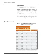
Страница 110: ...formed by putting a known amount of power into one end of the cable and verifying that after correcting for the cable losses the correct amount of power is coming out the other end Power Measurement Input Power 1W 5W 10W Reflected Power Reading Return Loss VSWR 0 001 0 005 0 01 30 0 1 07 0 002 0 010 0 02 27 0 1 09 0 003 0 015 0 03 25 2 1 12 0 004 0 020 0 04 24 0 1 14 0 005 0 025 0 05 23 0 1 15 0 0...

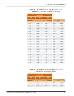
Страница 111: ...20 0 150 0 750 1 50 8 24 2 26 0 160 0 800 1 60 7 96 2 33 0 170 0 850 1 70 7 70 2 40 0 180 0 900 1 80 7 45 2 47 0 190 0 950 1 90 7 21 2 55 0 200 1 000 2 00 6 99 2 62 Table 15 Power Measurement to Return Loss and VSWR Conversion Table Part I continued Input Power 1W 5W 10W Reflected Power Reading Return Loss VSWR 0 20 1 05 2 10 6 78 2 69 0 22 1 10 2 20 6 58 2 77 Table 16 Power Measurement to Return ...

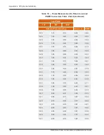
Страница 112: ... 3 70 0 34 1 70 3 40 4 69 3 80 0 35 1 75 3 50 4 56 3 90 0 36 1 80 3 60 4 44 4 00 0 37 1 85 3 70 4 32 4 11 0 38 1 90 3 80 4 20 4 21 0 39 1 95 3 90 4 09 4 33 0 40 2 00 4 00 3 98 4 44 0 41 2 05 4 10 3 87 4 56 0 42 2 10 4 20 3 77 4 68 0 43 2 15 4 30 3 67 4 81 0 44 2 20 4 40 3 57 4 94 0 45 2 25 4 50 3 47 5 08 0 46 2 30 4 60 3 37 5 22 0 47 2 35 4 70 3 28 5 36 Table 16 Power Measurement to Return Loss an...

Страница 113: ... Return Loss VSWR 0 48 2 40 4 80 3 19 5 51 0 49 2 45 4 90 3 10 5 67 Table 16 Power Measurement to Return Loss and VSWR Conversion Table Part II continued R450 Data Collector Installation and Maintenance Guide 93 Appendix A RF Antenna Installation ...

Страница 114: ... 1 848 1 160 0 595 280 6 468 4 060 2 083 90 2 079 1 305 0 670 290 6 699 4 205 2 158 100 2 310 1 450 0 744 300 6 930 4 350 2 232 110 2 541 1 595 0 818 310 7 161 4 495 2 306 120 2 772 1 740 0 893 320 7 392 4 640 2 381 130 3 003 1 885 0 967 330 7 623 4 785 2 455 140 3 234 2 030 1 042 340 7 854 4 930 2 530 150 3 465 2 175 1 116 350 8 085 5 075 2 604 160 3 696 2 320 1 190 360 8 316 5 220 2 678 170 3 92...

Страница 115: ...E or higher power element may be required Complete the following steps to use a Wattmeter and handheld to calculate VSWR 1 Connect the wattmeter and transceiver to the feed line in place of the R450 DC 2 Measure both the forward and reflected power 3 Find the return loss value using Table 15 on page 90 and Table 16 on page 91 4 Find the loss attributed to the coax using Table 17 on the previous pa...

Страница 116: ... in the plot area If there is press EXAM PLOT and it should go away 3 Allow the analyzer reading to stabilize between 10 and 20 seconds 4 Press EXAM PLOT to freeze the display 5 Move the cursor the vertical line in the middle of the screen using the FREQ arrows to approximately the R450 DC s frequency It moves to within 100KHz of a frequency 6 Read the value next to RETL on the display This is the...

Страница 117: ...ur Neptune sales representative If the unit or item requires reshipment use the original cardboard box and packing material In particular check to be sure that the N connector at the base of the antenna is not damaged This is much easier to check while the antenna is on the ground than after it is installed RF Antenna Installation Kit The RF 450 MHz antenna and the basic accessories are included w...

Страница 118: ... the installer UV Stable Cable Ties 8 and 12 20 32 cm and 30 48 cm Secure coax cable Cable Clips Various sizes Securing coax cable Concrete Blocks 8 X 8 X 16 20 32cm X 20 32cm X 40 64cm Ballast for the R450 DC Stand Weatherizing Kit PolyPhasor P N WK 1 or Times Microwave P N WK S 2 or Andrews P N 245171 Weatherproofing coax cable connections Electrical Tape Scotch Heavy Duty Vinyl Electrical Tape ...

Страница 119: ...e seated Complete these instructions to locate the site for the pole 1 Locate the conduit for the RF 450 MHz antenna cable and the trench where the cable for the RF 450 MHz antenna will be buried 2 Find a suitable spot close in this location to seat the RF antenna See Figure 73 RF 450 MHz antenna cable RF 450 MHz antenna protective conduit RF 450 MHz antenna cable trench Figure 73 RF 450 MHz Anten...

Страница 120: ...installation with the VSWR meter MISE en GARDE Vérifiez l installation du câble des connecteurs et de l antenne à l aide du rapport de tensions des ondes stationnaires To mount the RF 450 MHz antenna complete these steps 1 Assemble the RF 450 MHz antenna per the instructions included with the antenna kit See Figure 74 2 Use the mounting hardware included with the antenna to mount the antenna per t...

Страница 121: ...led inside a building The screen shield of the coaxial cable must be connected to the earth grounded at the entrance to the building This should be done in accordance with applicable national electrical installation codes Section 820 93 of the National Electrical Code ANSI NFPA 70 AVERTISSEMENT Soyez particulièrement attentif lorsque l antenne RF de l enregistreur de données R450 est installée à l...

Страница 122: ... be taken to try to resolve problems that could arise with your RF antenna Equipment Required The following items are required in order to troubleshoot the R450 DC l Keys to access the site and open the R450 DC cabinet l Digital volt Ohm multimeter l Socket and open end wrenches to install and remove the R450 DC l Small medium and large slot style screw drivers l 1 and 2 Phillips head screw driver...

Страница 123: ...e antenna and feed line combined The R450 DC s transmitter cannot be used to certify the antenna system The transmitter only transmits short packets approximately 50ms in length so taking an accurate reading of forward or reflected power cannot be done with standard equipment R450 Data Collector Installation and Maintenance Guide 103 Appendix A RF Antenna Installation ...

Страница 124: ...This page intentionally left blank Appendix A RF Antenna Installation 104 R450 Data Collector Installation and Maintenance Guide ...

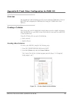
Страница 125: ...t Software provides valuable information about the R450 DCs in your R450 System On this tab you can search for an R450 DC or create an R450 DC Using the Collector tab you can do the following l Create collector l Search collectors Creating a New Collector To create a new R450 DC complete the following steps 1 Open the N_SIGHT R450 Host Software on the PC 2 Select the Collector tab and click Create...

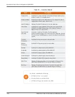
Страница 126: ...requency used to transmit data Receive Frequency Indicates the frequency used to receive data Latitude Indicates the actual latitude of the R450 DC Longitude Indicates the actual longitude of the R450 DC Power Indicates the power used by the R450 DC Antenna Height Indicates the actual height of the RF antenna Daily Reboot Indicates if the R450 DC requires a daily reboot Start Time Displays the beg...

Страница 127: ...l Mobile NTP Server Indicates a server that uses NTP Network Time protocol Its purpose is to keep the clock accurate Primary DNS Server Indicates the primary server the first DNS Domain Name System server queried when trying to resolve a server name You can supply the name rather than the IP address for example Chicago rather than 10 10 10 10 Secondary DNS Server Indicates the secondary server the...

Страница 128: ...or window appears with the existing information for the collector 2 Edit and change the appropriate information on both the Collector Details tab and the Collector Network Settings tab 3 When complete click Save to display the new information for the collector The changes you made are saved for the selected collector Deleting a Collector To delete a collector complete the following steps 1 On the ...

Страница 129: ...or the R450 DC l Collector Name l Synchro User l Collector ID 2 Type all or part of the search criteria you selected in the previous step in the search area provided See Figure 81 Everything matching your search criteria appears in the collector list on the Collector tab with the detailed information for the collector appearing in the lower half of the page See Figure 82 on page 110 R450 Data Coll...

Страница 130: ... ability to build a USB drive that can be inserted into a replacement collector for automatic configuration in order to mimic an old collector Complete the following steps to add an USB drive 1 Select the R450 DC to upload data to the USB drive from the Collector tab 2 Click Build USB A confirmation message appears similar to the following 3 Click OK to build the drive 110 R450 Data Collector Inst...

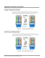
Страница 131: ...using the T 568B wiring standard for both ends One end should already be pre terminated to the switch or hub Figure 83 Straight Through Ethernet Cable RJ 45 Crossover Ethernet Cable On some occasions a Crossover Ethernet Cable is required If you require a cable to connect two Ethernet devices directly together without a hub or when you connect two hubs together you will need to use a crossover cab...

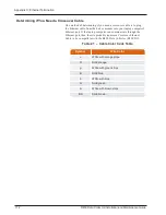
Страница 132: ...hrough the Ethernet port then the site probably requires a Crossover Ethernet Cable to be compatible with the R450 Data Collector R450 DC Symbol Wire Color o White with orange stripe O Solid orange g White with green stripe B Solid blue b White with blue G Solid green br White with brown stripe BR Solid brown Table 21 Cable Color Code Table 112 R450 Data Collector Installation and Maintenance Guid...

Страница 133: ...nalytics system to convert it into actionable information that supports the efficient management of the utility AMR Automatic Meter Reading The automated process of reading meters APN Access Point Name AWG American Wire Gauge B ballast Heavy material used to secure the stability of the equipment stand For the R450 System concrete blocks are used for the ballast C CDMA Code Division Multiple Access...

Страница 134: ...C is a device that collects meter reading data from Neptune s absolute encoder register interfacing with Neptune s new R450 MIU and transmits the data for collection This unit receives the data and stores data to be downloaded through the host software DHCP Dynamic Host Configuration Protocol F FCC Federal Communication Commission G GPRS General Packet Radio Service modem 114 R450 Data Collector I...

Страница 135: ...l Code R R450 System R450 System is a fixed network AMI system for targeted applications Allows a utility to conduct meter reading operations automatically ensuring maximum collection of the data S serial number A unique identification number given to each product at the factory SIM System Information Manager R450 Data Collector Installation and Maintenance Guide 115 ...

Страница 136: ...computers and devices UV Ultraviolet V voltmeter An instrument used for measuring electrical potential difference between two points in an electric circuit VSWR Voltage Standing Wave Ratio The ratio of the amplitude of a partial standing wave at an antinode maximum to the amplitude at an adjacent node minimum in an electrical transmission line W WiFi Wireless Fidelity modem 116 R450 Data Collector...

Страница 137: ...iFi 9 APN 32 assembly accessories CDMA 10 Ethernet 9 GPRS 8 WiFi 9 auto connect 68 AWG 20 B backhaul modem 76 modem connectivity 80 type 2 ballast 98 battery 46 fuse 61 installing and wiring 60 safety checklist 49 spill kit 49 bonded 87 branch circuit breaker 55 breaker switch 25 28 C cable antenna 15 65 clips 13 Ethernet 65 66 111 serial 67 Cal Amp landcell modem 76 79 calculating VSWR 96 CDMA ac...

Страница 138: ...ector USB flash drive 27 GPRS modem 32 connectivity 80 connectors 88 conversion table 90 91 CPU board 27 30 76 78 creating collector 105 customer support 84 D Digital Volt Ohm Multimeter 79 disconnects 56 E electrical codes 25 encoder register 1 Ethernet 2 9 backhaul 30 cable 26 32 cable RJ 45 crossover 111 cable straight through 111 connection 65 hardware kit 9 kit 9 parts list 9 port 67 112 term...

Страница 139: ...ite selection 3 interference 6 internal ground lug 24 26 inverter 62 L LED 62 lightning arrestors 8 link integrity light 30 M magnet 14 31 81 materials 13 MIU 1 placement 7 swipe 30 modem Cal Amp 74 CDMA 2 10 EVDO 69 GPRS 2 8 homepage 68 Sierra Wireless 67 Sprint 69 Verizon 70 WiFi 2 9 monitoring LEDs 54 mounting antenna 20 85 bracket 65 plate 66 67 pole 57 RF 450 antenna 100 UPS 57 mounting brack...

Страница 140: ...mounting 57 steel or concrete 57 wooden 58 power light GPRS 29 WiFi 29 power measurement 90 power supply 43 PPP status 70 72 primary DNS server 107 provisioning tab 69 R R450 DC 1 65 kit 8 mounting 4 performance issues 6 potential problems 74 product description 1 securing 33 stand 5 synchronizing 32 transmitter 102 R450 MIU performance issues 6 radio power 76 receiver recommended 7 sensitivity 7 ...

Страница 141: ...spectrum analyzer 6 Sprint modem 69 stable ties 13 stand R450 DC 5 storage 12 storm activity 8 structure 85 strut channels 16 21 clamp 8 10 16 18 syncing 81 T testing connections 29 tool kit 13 tools 13 tools and materials 98 tower 85 transceiver 95 trench 15 99 troubleshooting 73 equipment required 73 PC Notebook Configuration 74 storm damage 75 voltage checks 77 tune knob 82 U unlicensed equipme...

Страница 142: ...ection checklist 52 USB 67 building for collector configuration 110 flash drive 27 30 ports 27 V Verizon modem 70 voltmeter 61 VSWR 82 90 95 W wall mounting 57 WAN connection 107 wattmeter 95 weatherizing antenna connection 24 cable connections 23 102 kit 13 WiFi modem 9 wiring connectors 59 122 R450 Data Collector Installation and Maintenance Guide ...

Страница 143: ......
Страница 144: ...5M9 Canada Tel 905 858 4211 Fax 905 858 0428 Neptune Technology Group Inc Ejèrcito Nacional No 418 Piso 12 Desp 1201 1202 Col Chapultepec Morales Delegación Miguel Hidalgo 11570 Mèxico Distrito Federal T 525 55203 5294 525 55203 5708 IM R450 Data Collector 05 2020 PartNo 12835 001 Copyright2006 2020 Neptune Technology Group Inc Neptune is a registered trademark ofNeptune Technology Group Inc ...

Отзывы: