CHAPTER 3. GENERAL HARDWARE INFORMATION
3.2. LC DISPLAY
Note:
With this method, the robot is shut down by cutting the power supply. This may damage the on-board
computer’s hard- and software.
3.2 LC Display
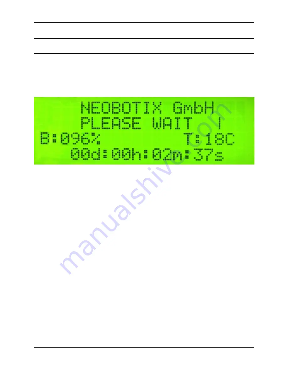
3.2.1 Main View
3.2.1.1 Messages
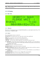
The first line can be used to print messages sent from ROS, PlatformPilot or any other high level control software. The
default message is “NEOBOTIX GmbH”.
3.2.1.2 Status
The second line indicates the robot’s current status.
PLEASE WAIT
The control software is not yet connected to the robot’s main control board.
READY
The control software is active and the robot is fully operational.
EMERGENCY STOP
One of the emergency stop buttons has been pressed.
TURN KEY
→
Reset the safety system by turning the key switch clockwise for about one second.
SCANNER STOP
An obstacle has been detected within the laser scanner’s safety field. As soon as the obstacle has
been removed, the safety system will be reset automatically. If a Flexi Soft safety controller is installed, all stops
are indicated with this message.
CHARGING
The robot is currently charging its batteries.
SHUTDOWN IN XXs
The robot will turn itself off in a few seconds.
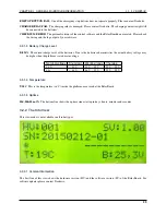
BATTERY VOLTAGE LOW
The battery voltage is critically low and the robot will soon shut down to prevent a
deep discharge. Further information can be found in the next section.
MOTOR ERROR
At least one motor is reporting an error. This state is quit automatically as soon as all motors are
operational again.
SAFETY RELAY FAIL
One of the safety relays is damaged. Please contact Neobotix.
POWER RELAY FAIL
The power relays are damaged. Please contact Neobotix.
22
Содержание MMO-700
Страница 1: ...MMO 700 Neobotix GmbH Apr 14 2022 ...
Страница 11: ...CHAPTER 1 MMO 700 1 6 TRANSPORT Fig 3 Position of the auxiliary batteries and battery connectors 7 ...
Страница 33: ...CHAPTER 3 GENERAL HARDWARE INFORMATION 3 4 CHARGING STATIONS Fig 2 Position of the main power switch X 29 ...
Страница 52: ...CHAPTER 4 OMNI DRIVE MODULE 4 4 ELECTRICAL INSTALLATION Fig 1 Dimensions of the Omni Drive Module 48 ...
Страница 53: ...CHAPTER 4 OMNI DRIVE MODULE 4 4 ELECTRICAL INSTALLATION Fig 2 Bottom view of the Omni Drive Module 49 ...
Страница 54: ...CHAPTER 4 OMNI DRIVE MODULE 4 4 ELECTRICAL INSTALLATION Fig 3 Top view of the Omni Drive Module 50 ...


