CHAPTER 4. OMNI DRIVE MODULE
4.6. MAINTENANCE
The
Feedback
velocities define the range in which the motor is allowed to operate without raising an error. Therefore
the Feedback limits should be set wider than the command limits.
The
Stop
deceleration is the deceleration that is used when a stop command is sent to the amplifier. This deceleration
can be much higher than the values defined as normal acceleration and deceleration. It is meant to provide the fastest
yet safest stopping of the axis in case of an emergency.
4.5.3.3 Control Loop Parameters
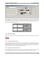
The internal parameters of the velocity and position control loop can be changed in the Digital Filters tab.
The values of the current control loop should not be changed manually.
In the unlikely case that the behaviour of the Omni-Drive-Module does not meet the application’s requirements the
internal parameters may be changed carefully. Please consult your local Elmo Motion Control department before
modifying these values.
4.5.4 Testing and Debugging
The
Test Motion area
in the Profile tab can be used to move the motor under manual control for testing purposes.
Activate Jogging mode to make the motor rotate continuously with the given Speed, or deactivate the check-box to
move the motor to the given Position. Simply click the Go button to start the motion and Stop to set the velocity back
to zero.
The Composer also offers a function to record high definition measurements of the motor’s movements and to plot
these data graphically. Please contact Neobotix or Elmo Motion Control if you need further information on this topic.
4.6 Maintenance
The Neobotix Omni-Drive-Module does not require excessive maintenance. Please check the following details ap-
proximately every month to ensure the best function and a long life expectancy.
4.6.1 Cleaning
The gearbox housing of the Omni-Drive-Module is completely sealed and will not be affected by dirt. Nevertheless
it is recommended to regularly remove dust and dirt in order to optimise heat dissipation, especially if the module is
integrated into a closed hull and has only limited convection cooling.
Please keep the PCB and the amplifiers as clean as possible. This will prevent short circuiting and damage to the
electronics.
Depending on the environment the module is used in, some amount of hairs and dust will accumulate on the wheel’s
axle near the bearing. Please clean this area regularly to avoid damage to the seals of the ball bearing and to minimise
friction.
4.6.2 Traction Wheel
The traction wheel is very hard-wearing and not expected to show any signs of damage or wear within the expected
lifetime of the module. In case you find any signs of wear, please contact Neobotix.
60
Содержание MMO-700
Страница 1: ...MMO 700 Neobotix GmbH Apr 14 2022 ...
Страница 11: ...CHAPTER 1 MMO 700 1 6 TRANSPORT Fig 3 Position of the auxiliary batteries and battery connectors 7 ...
Страница 33: ...CHAPTER 3 GENERAL HARDWARE INFORMATION 3 4 CHARGING STATIONS Fig 2 Position of the main power switch X 29 ...
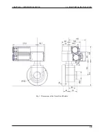
Страница 52: ...CHAPTER 4 OMNI DRIVE MODULE 4 4 ELECTRICAL INSTALLATION Fig 1 Dimensions of the Omni Drive Module 48 ...
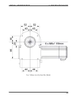
Страница 53: ...CHAPTER 4 OMNI DRIVE MODULE 4 4 ELECTRICAL INSTALLATION Fig 2 Bottom view of the Omni Drive Module 49 ...
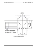
Страница 54: ...CHAPTER 4 OMNI DRIVE MODULE 4 4 ELECTRICAL INSTALLATION Fig 3 Top view of the Omni Drive Module 50 ...

