


CHAPTER 3. GENERAL HARDWARE INFORMATION
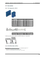
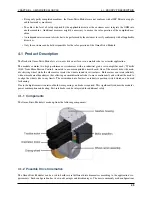
3.5. CONNECTORS
Pins (in 2 rows)
Würth Elektronik
2
649002113322
4
649004113322
6
649006113322
8
649008113322
10
649010113322
16
649016113322
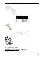
Crimp contacts
Würth Elektronik
AWG 24-18
64900613722
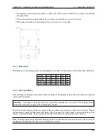
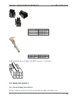
In Neobotix products the pin assignment of the MPC4 connectors is as shown below.
3.5.3 Würth Elektronik - MPC3
Please check the
Würth Elektronik online catalogue
for details on the
6
https://www.we-online.de/web/de/wuerth_elektronik/start.php
7
https://www.we-online.de/katalog/de/em/connectors/wire-to-board/wr_mpc3/
31
Содержание MMO-700
Страница 1: ...MMO 700 Neobotix GmbH Apr 14 2022 ...
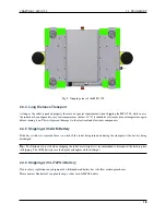
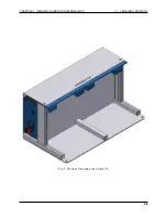
Страница 11: ...CHAPTER 1 MMO 700 1 6 TRANSPORT Fig 3 Position of the auxiliary batteries and battery connectors 7 ...
Страница 33: ...CHAPTER 3 GENERAL HARDWARE INFORMATION 3 4 CHARGING STATIONS Fig 2 Position of the main power switch X 29 ...
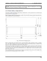
Страница 52: ...CHAPTER 4 OMNI DRIVE MODULE 4 4 ELECTRICAL INSTALLATION Fig 1 Dimensions of the Omni Drive Module 48 ...
Страница 53: ...CHAPTER 4 OMNI DRIVE MODULE 4 4 ELECTRICAL INSTALLATION Fig 2 Bottom view of the Omni Drive Module 49 ...
Страница 54: ...CHAPTER 4 OMNI DRIVE MODULE 4 4 ELECTRICAL INSTALLATION Fig 3 Top view of the Omni Drive Module 50 ...