NEC SL1100
Issue 6.0
Networking Manual
6 - 21
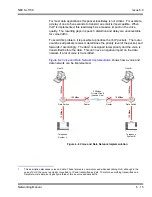
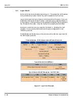
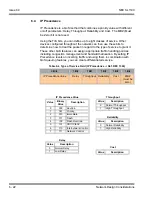
Listed below are the fields used in
Figure 6-7 Layer 3 QoS Example
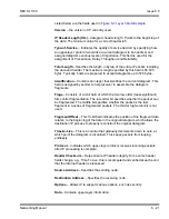
Version
– the version of IP currently used.
IP Header Length (IHL)
– datagram header length. Points to the beginning of
the data. The minimum value for a correct header is 5.
Type-of-Service
– Indicates the quality of service desired by specifying how
an upper-layer protocol would like a current datagram to be handled, and
assigns datagrams various levels of importance. This field is used for the
assignment of Precedence, Delay, Throughput and Reliability.
Total Length
– Specifies the length, in bytes, of the entire IP packet, including
the data and header. The maximum length specified by this field is 65,535
bytes. Typically, hosts are prepared to accept datagrams up to 576 bytes.
Identification
– Contains an integer that identifies the current datagram. This
field is assigned by sender to help receiver to assemble the datagram
fragments.
Flags
– Consists of a 3-bit field of which the two low-order (least-significant)
bits control fragmentation. The low-order bit specifies whether the packet can
be fragmented. The middle bit specifies whether the packet is the last
fragment in a series of fragmented packets. The third or high-order bit is not
used.
Fragment Offset
– This 13-bit field indicates the position of the fragment data
relative to the beginning of the data in the original datagram, which allows the
destination IP process to properly reconstruct the original datagram.
Time-to-Live
– This is a counter that gradually decrements down to zero, at
which point the datagram is discarded. This keeps packets from looping
endlessly.
Protocol
– Indicates which upper-layer protocol receives incoming packets
after IP processing is complete.
Header Checksum
– Helps ensure IP header integrity. Since some header
fields change, e.g., Time To Live, this is recomputed and verified at each point
that the Internet header is processed.
Source Address
– Specifies the sending node.
Destination Address
– Specifies the receiving node.
Options
– Allows IP to support various options, such as security.
Data
– Contains upper-layer information.
Содержание SL1100
Страница 1: ...Networking Manual NDA 31190 Issue 6 0 SL1100...
Страница 2: ......
Страница 4: ......
Страница 22: ...Issue 6 0 NEC SL1100 1 2 Introduction THIS PAGE INTENTIONALLY LEFT BLANK...
Страница 62: ...Issue 6 0 NEC SL1100 5 30 Programming THIS PAGE INTENTIONALLY LEFT BLANK...
Страница 81: ...NEC SL1100 Issue 6 0 Networking Manual 6 19 Ethernet Frame Example Layer 2 QoS Enabled Continued...
Страница 94: ...Issue 6 0 NEC SL1100 6 32 Network Design Considerations THIS PAGE INTENTIONALLY LEFT BLANK...
Страница 134: ...Issue 6 0 NEC SL1100 8 10 DHCP Client THIS PAGE INTENTIONALLY LEFT BLANK...
Страница 159: ...NEC SL1100 Issue 6 0 Networking Manual 9 25 Figure 9 7 Log In to IP Phone...
Страница 181: ...NEC SL1100 Issue 6 0 Networking Manual 9 47 Figure 9 25 IP System Operation Setup...
Страница 206: ...Issue 6 0 NEC SL1100 9 72 IP Multiline Station SIP Figure 9 36 NAPT Configuration Example...
Страница 230: ...Issue 6 0 NEC SL1100 10 18 IP Single Line Telephone THIS PAGE INTENTIONALLY LEFT BLANK...
Страница 232: ...Issue 6 0 NEC SL1100 11 2 NAPT Figure 11 1 NAPT Configuration Example...
Страница 242: ...Issue 6 0 NEC SL1100 12 4 All DSP Busy Indication THIS PAGE INTENTIONALLY LEFT BLANK...
Страница 290: ...Issue 6 0 NEC SL1100 13 48 SL Net THIS PAGE INTENTIONALLY LEFT BLANK...
Страница 291: ......
Страница 292: ...SL1100 Networking Manual NEC Corporation of America Issue 6 0...

