4
NO
NO
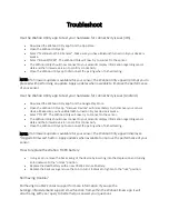
When the main power supply
Is the potential kept at “H” at
Fault in IC9501 and its
is turned ON, is it possible to
Pins 79 and 80 (MAIN) of
peripheral circuits
hear the sound of the AC relay
IC9501?
to turn ON?
YES
YES
NO
Is the potential kept at “H” at
The POWER unit is out of
Pins
4
and
5
of the PM
order when the PM connector
connector?
is pulled out and the potential
is turned at “H” at Pins
4
and
YES
5
(MAIN). If the potential
remains to stay at “L” this is
Fault in the POWER unit
due to a fault in IC9501 and
its peripheral circuits.
YES
It takes more than 5 seconds
Fault in IC9501 (MAIN) and
to attain OFF after the main
its peripheral circuits
power supply is turned ON.
NO
NO
Is the potential kept at “H” at
Pins
4
and
5
of the PM
connector?
YES
NO
Is the potential kept at “H” at
Fault around the MODULE
Pin 21 of the PD connector?
circuit
YES
YES
Is the power supply built up
Fault in the MODULE circuit
when the PD, PH, and AD
and the HV system or the
connectors are disconnected?
peripheral circuit of D+5V in
the POWER unit
NO
Try to disconnect the respective PV, PQ, PN, and PA connectors
from one after another (others left connected) and confirm if the
power supply is available. If the power supply is found available,
the circuits beyond the disconnected connectors are out of order.
If no operation is found, the POWER unit is out of order.
4-15
TROUBLESHOOTING
▼
▼
▼
▼
▼
▼
▼
▼
▼
▼
▼
▼
▼
▼
▼
Содержание PlasmaSync PX-42VM1G
Страница 10: ...NEC Technologies PlasmaSync Plasma Monitor User s Manual...
Страница 118: ...METHOD OF DISASSEMBLY 7 1 1 Diagonal view of the main unit rear panel...
Страница 123: ...METHOD OF DISASSEMBLY 7 6 A01 C04 4 MAIN PWB ASSY 1 Remove the screw C04 and take out the MAIN PWB ASSY A01...
Страница 124: ...METHOD OF DISASSEMBLY 7 7 5 POWER UNIT 1 Remove the eight screws S02 and take out the POWER UNIT A10 A10 S02...
Страница 128: ...METHOD OF DISASSEMBLY 7 11 9 BRACKET MAIN 1 Remove the six screws S02 and take out the BRACKET MAIN M11 S02 M11...
Страница 134: ...MEMO...
Страница 135: ...DISASSEMBLY 8 1 S01 S01 M05 M06 M07 A06 S01 S01 S01 S01 S01 M01 M04 M06 S01 A04 P01 M03 S10 S03 S01 M02...
Страница 137: ...9 1 PACKAGING Packing details A Safety bracket SASSY B 1 Safety bag SASSY...
Страница 139: ...D CUSHION CARTON BOX 9 3 PACKAGING...
Страница 141: ...9 5 PACKAGING F CARTON BOX OUT...
Страница 147: ...CONNECTION DIAGRAMS 11 1...
Страница 148: ...BLOCK DIAGRAMS 12 1 MAIN PWB BLOCK...
Страница 149: ...BLOCK DIAGRAMS 12 2 VIDEO BLOCK...
Страница 150: ...BLOCK DIAGRAMS 12 3 AUDIO BLOCK...
Страница 151: ......
Страница 152: ......
Страница 153: ......
Страница 154: ......
Страница 155: ......
Страница 156: ......
Страница 157: ......
Страница 158: ......
Страница 159: ......
Страница 160: ......
Страница 161: ......
Страница 162: ......
Страница 163: ......
Страница 164: ......
Страница 165: ......
Страница 166: ......
Страница 167: ......
Страница 168: ......
Страница 169: ......
Страница 170: ......
Страница 171: ......
Страница 172: ......