background image

User’s Manual

Target device
 V850E/MS1

TM

IE-703102-MC-EM1,
IE-703102-MC-EM1-A

In-circuit Emulator Optional Board

1991

©

Document No.   U13876EJ1V0UM00 (1st edition)
Date Published   December  1998 N  CP(K)

Printed in Japan

1998

Содержание IE-703102-MC-EM1

Страница 1: ... Manual Target device V850E MS1TM IE 703102 MC EM1 IE 703102 MC EM1 A In circuit Emulator Optional Board 1991 Document No U13876EJ1V0UM00 1st edition Date Published December 1998 N CP K Printed in Japan 1998 ...

Страница 2: ...2 MEMO ...

Страница 3: ...ange without notice No part of this document may be copied or reproduced in any form or by any means without the prior written consent of NEC Corporation NEC Corporation assumes no responsibility for any errors which may appear in this document NEC Corporation does not assume any liability for infringement of patents copyrights or other intellectual property rights of third parties by or arising f...

Страница 4: ...ny Tel 0211 65 03 02 Fax 0211 65 03 490 NEC Electronics UK Ltd Milton Keynes UK Tel 01908 691 133 Fax 01908 670 290 NEC Electronics Italiana s r l Milano Italy Tel 02 66 75 41 Fax 02 66 75 42 99 NEC Electronics Germany GmbH Benelux Office Eindhoven The Netherlands Tel 040 2445845 Fax 040 2444580 NEC Electronics France S A Velizy Villacoublay France Tel 01 30 67 58 00 Fax 01 30 67 58 99 NEC Electro...

Страница 5: ...A For the names and functions and the connection of parts refer to the IE 703102 MC User s Manual which is a separate volume To understand the basic specifications and operation methods broadly Read this manual in the order listed in CONTENTS To know the operation methods and command functions of the IE 703102 MC IE 703102 MC EM1 and IE 703102 MC EM1 A Read the user s manual of the debugger separa...

Страница 6: ...red µPD703100 A40 703101 A33 703102 A33 Data Sheet To be prepared µPD70F3102 33 Data Sheet U13844E µPD70F3102 A33 Data Sheet U13845E Documents related to development tools User s Manual Product Name Document Number IE 703102 MC In circuit emulator U13875E IE 703102 MC EM1 IE 703102 MC EM1 A In circuit emulator optional board This manual Operation UNIX TM based U12839E Operation Windows TM based U1...

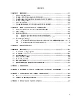
Страница 7: ...en emulator is used connected to target system 22 2 4 Power Supply Settings 23 2 4 1 JP2 setting when the emulator operates as a stand alone unit and target system power is off 23 2 4 2 JP2 setting when power of the target system is on 23 CHAPTER 3 FACTORY SETTINGS 25 CHAPTER 4 CAUTIONS 27 4 1 VDD and HVDD of Target System 27 4 2 X1 Signal 27 4 3 Pin Termination 28 4 4 Internal RAM and ROM 29 4 5 ...

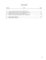
Страница 8: ... Operates as a Stand Alone Unit and Target System Power is Off 23 2 3 Power Supply Setting When Power of the Target System is On 23 4 1 Schematic Diagram of Power Supply Flow 27 4 2 Diagram of X1 Signal Flow 28 4 3 Circuit Diagram of CKSEL Pin 28 4 4 Circuit Diagram of Port 4 to 6 A and B 30 C 1 Mounting of NQPACK144SD 43 C 2 Mounting Device 44 C 3 NQPACK100SD and Device Pin 44 D 1 Mounting Method...

Страница 9: ...Unit 21 2 2 Clock Setting When the Emulator is Used in Target System Connection 21 2 3 MODE Pin Setting when Emulator is Used as Stand Alone Unit 22 2 4 MODE Pin Setting when Emulator is Used Connected to Target System 22 4 1 Memory Capacity Limitation List 29 4 2 Bus Interface Pin Operation List 31 ...

Страница 10: ...10 MEMO ...

Страница 11: ...ng the V850E MS1 IE 703102 MC EM1 is an optional board when HVDD 5 V IE 703102 MC EM1 A is an optional board when HVDD 3 3 V In this manual the basic setup sequences and switch settings of the IE 703102 MC EM1 when connecting it to the IE 703102 MC are described For the names and functions of the parts of the IE 703102 MC and for the connection of elements refer to the IE 703102 MC User s Manual U...

Страница 12: ... 9800 series C bus Note 2 PC for IBM PC ATTM compatible ISA bus Note 2 IE 70000 PCI IF for PCI bus IE 70000 CD IF A for PCMCIA socket Network module IE 70000 MC SV3 The module is used when a workstation controls the IE 703102 MC via ethernetTM Power adapter IE 70000 MC PS B AC adapter dedicated to the NEC s in circuit emulator Separately sold hardware 1 1 Hardware Configuration Notes 1 For further...

Страница 13: ...ESET NMI WAIT HLDRQ Two methods of connection to target system Direct connection of the IE 703102 MC EM1 Attach an extension probe sold separetely to the connection tab of the IE 703102 MC EM1 Dimensions of the IE 703102 MC EM1 are as follows Parameter Value Power dissipation 0 4 W at 40 MHz operation frequency Note Height 15 mm Length 207 mm External dimensions Refer to APPENDIX A DIMENSIONS Widt...

Страница 14: ...Memory access detection Coverage memory capacity External memory 1 Mbyte Trace memory capacity 168 bits 32 Kframes Time measurement function Can be measured with time tag and timers 3 lines 8 bit external trace is possible External logic probe Event setting for trace break is possible Event break Step execution break Forced break Break function Fail safe break Illegal access to peripheral I O Acce...

Страница 15: ...th IE 703102 MC 5 In circuit emulator IE 703102 MC sold separately 6 In circuit emulator option board IE 703102 MC EM1 7 External logic probe included with IE 703102 MC 8 Extension probe SC 144SD SC 144SD PR sold separately 9 Connector for emulator connection YQPACK144SD included 10 Connector for target connection NQPACK144SD included 11 Power adapter IE 70000 MC PS B sold separately 12 AC100 V po...

Страница 16: ...this manual and connector accessories In case of missing or damaged contents contact an NEC sales representative or an NEC distributor Figure 1 2 Contents in Carton 1 IE 703102 MC EM1 2 Accessory bag 3 Guarantee card 4 Packing list 1 IE 703102 MC EM1 1 2 Accessory bag 1 3 Guarantee card 1 4 Packing list 1 Make sure that the accessory bag contains this manual and an accessory list 1 sheet ...

Страница 17: ...ocket at the back of the pod refer to Figure 1 3 c When connecting position the IE 703102 MC and IE 703102 MC EM1 so that they are horizontal Spacers can be connected to fix the pod refer to APPENDIX D MOUNTING OF PLASTIC SPACER 4 Set the PGA socket lever of the IE 703102 MC EM1 to the CLOSE position as shown in Figure 1 3 b 5 Fix the IE 703102 MC EM1 between the pod covers upper and lower with ny...

Страница 18: ...EW 18 Figure 1 3 Connection between IE 703102 MC and IE 703102 MC EM1 2 2 b PGA Socket Lever of IE 703102 MC EM1 c Connecting part IE 703102 MC EM1 Pin A1 location Insertion guide IE 703102 MC insertion area CLOSE OPEN ...

Страница 19: ...he IE 703102 MC User s Manual 2 1 Component Name and Function of IE 703102 MC EM1 Figure 2 1 IE 703102 MC EM1 a Top View b Bottom View TP1 Connector for connection to IE 703102 MC SW1 DIRECT PLL LED CKSEL Green V850E MS1 I O chip TP2 TP3 TP4 TP5 TP6 JP1 1 2 7 8 OSC Direction of pin 1 of the connector for target connection Direction of pin 1 of the connector for target connection Connector for targ...

Страница 20: ...clock supply source for details refer to 2 2 Clock Settings 4 JP2 This is a switch jumper for the power supply for details refer to 2 4 Power Supply Settings 5 LED CKSEL Green LED Status When Used as a Stand Alone Unit When Used in Target System Connection ON SW1 DIRECT The CKSEL signal from the target system is high OFF SW1 PLL The CKSEL signal from the target system is low 6 Connector for IE 703...

Страница 21: ... PLL Internal clock Direct mode 1 2 7 8 DIRECT PLL Note Setting any other state is prohibited Table 2 2 Clock Setting When the Emulator is Used in Target System Connection Clock Supply Source Setting Clock Mode Setting Clock Supply Method JP1 Setting Note 1 SW1 Setting CKSEL Setting CKSEL Setting of Target System PLL mode DIRECT PLL Low level Internal clock target clock Note 2 Direct mode 1 2 7 8 ...

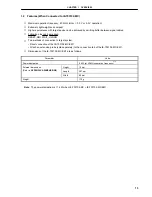
Страница 22: ...e chip mode 0 Low level input High level input 2 3 2 MODE pin setting when emulator is used connected to target system When the emulator is connected to a target system set the MODE pins of the target system as follows based on the emulator operations The MODE2 and MODE3 signals in the target system are not used in the emulator Table 2 4 MODE Pin Setting when Emulator is Used Connected to Target S...

Страница 23: ...on the product the condition of the power is as follows IE 703102 MC EM1 VDD 3 3 V HVDD 5 0 V IE 703102 MC EM1 A VDD 3 3 V HVDD 3 3V Figure 2 2 shows the JP2 setting Caution If the JP2 setting is incorrect the emulator may be damaged Figure 2 2 Power Supply Settings When the Emulator Operates as a Stand Alone Unit and Target System Power is Off 1 2 3 4 JP2 Set both 1 2 and 3 4 as open 2 4 2 JP2 se...

Страница 24: ...24 MEMO ...

Страница 25: ...ted JP2 1 2 3 4 Setting that supplies the IE 703102 MC EM1 with the power of the emulator when the emulator operates as a stand alone unit and target system power is off SW1 DIRECT PLL Set to PLL mode Crystal oscillator 8 000 MHz crystal oscillator is mounted If SW1 is set to the factory setting the CPU operates at 40 MHz ...

Страница 26: ...26 MEMO ...

Страница 27: ... is off and operates with the 3 3 V power supply Figure 4 1 Schematic Diagram of Power Supply Flow IE 703102 MC EM1 I O chip Target system CVDD VDD HVDD Relay Power supply circuit Evaluation chip IE 703102 MC 1 2 3 4 JP2 1 2 3 4 JP2 4 2 X1 Signal The input signal X1 signal from the target system is delayed for tpLH tpHL 13 2 ns MAX because it passes through VHC157 before it is input to the I O chi...

Страница 28: ...lator is single chip mode 0 The MODE0 to MODE3 pins are connected as follows MODE0 Connected to VSS via a resistor 33 kΩ Pull down MODE1 Connected to VDD via a resistor 5 1 kΩ Pull up MODE2 Unconnected MODE3 Unconnected 2 RESET pin This pin is connected to VDD via a resistor 5 1 kΩ Pull up 3 CKSEL pin Pull up pull down switching is possible with SW1 Figure 4 3 Circuit Diagram of CKSEL Pin VHCT541 ...

Страница 29: ...ry Capacity Limitation List a iRAM capacity Unit byte b iROM capacity Unit byte Target Device Emulator Target Device Emulator Emulation Memory 1 K 1 K 1 K to 32 K 32 K 2 K 2 K 33 K to 64 K 64 K 3 K 3 K 65 K to 128 K V850E MS1 128 K 4 K V850E MS1 4 K 129 K to 256 K 256 K 5 K to 6 K 6 K 257 K to 512 K 512 KNote 7 K to 8 K 8 K 9 K to 10 K 10 K 11 K to 12 K 12 K 13 K to 16 K 16 K 17 K to 20 K 20 K 21 ...

Страница 30: ...6 A and B are connected to VHCT541 VHC541 and VHCT00 respectively Figure 4 4 Circuit Diagram of Port 4 to 6 A and B Evaluation chip Port 4 Port 5 Port 6 Port A Port B VHCT541 VHC541 VHCT541 VHC541 VHCT00 VHCT541 VHCT541 Emulation memory 2 Mbytes Target system ...

Страница 31: ...ing for Emulator Command R R W R W R W R W A0 to A23 Note Note Note Note D0 to D15 Hi Z Hi Z Note Note WE H H H Note OE H H H Note RD H H H Note ADV BCYST Note H Note Note UWR UCAS H H H Note LWR LCAS H H H Note IORD H H H Note IOWR H H H Note CS0 to CS7 H H H Note RAS0 to RAS7 H H H Note REFRQ H H H Note WAIT Invalid Note Maskable HLDRQ Maskable Maskable Maskable HLDAK Note Note Note Note Perform...

Страница 32: ... Note Note Note D0 to D15 Hi Z Note Note WE H H Note OE H H Note RD H H Note ADV BCYST H Note Note UWR UCAS H H Note LWR LCAS H H Note IROD H H Note IOWR H H Note CS0 to CS7 H H Note RAS0 to RAS7 H H Note REFRQ H H Note WAIT Note Maskable HLDRQ Maskable Maskable HLDAK Note Note Note Performs the same operation as the cycle that is generated by the target device program execution Remarks 1 F Fetch ...

Страница 33: ...e HLDAK Note Note Performs the same operation as the cycle that is generated by the target device program execution 4 7 Emulation Memory Operation Timing Difference When the area of the DRAM synchronous flash memory or page ROM in the target system has been allocated to the emulation memory the operation timing is the SRAM access timing When measuring the performance by using the emulation memory ...

Страница 34: ...34 MEMO ...

Страница 35: ...APPENDIX A DIMENSIONS 1 IE 703102 MC IE 703102 MC EM1 Unit mm 461 55 166 58 8 57 90 27 240 Top View Side View IE 703102 MC EM1 IE 703102 MC Bottom View Top View 15 88 207 29 0 96 37 5 29 0 Pin 1 direction ...

Страница 36: ...APPENDIX A DIMENSIONS 36 2 SC 144SD Unit mm 109 144 72 37 108 1 73 36 43 13 13 40 130 43 213 46 ...

Страница 37: ...w Side View Bottom View 5 5 1 85 0 2 21 05 0 5 0 5 0 18 3 9 3 7 1 2 9 45 1 36 73 108 37 72 144 109 23 0 12 0 20 1 4 φ2 0 Height of projection 1 8 0 2 73 72 109 144 1 37 36 108 7 0 7 0 27 0 0 5 35 17 5 0 5 18 9 26 2 20 1 2 5 2 5 22 65 3 R1 5 3 φ1 0 C1 5 0 3 ...

Страница 38: ...iew Side View Bottom View 3 7 3 1 2 5 9 0 2 2 3 9 1 2 7 4 2 3 0 3 0 25 0 25 0 3 144 109 108 73 72 37 1 36 22 8 19 6 C1 5 20 8 0 2 109 144 7 0 22 65 0 5 35 17 5 0 5 4 φ2 2 C2 0 108 7 0 27 0 29 0 19 4 73 72 37 4 R1 5 3 R2 5 1 36 16 4 18 8 21 2 23 6 3 φ1 0 ...

Страница 39: ...Side View Bottom View 7 0 0 1 22 65 0 15 0 5 35 17 5 0 1 7 0 27 0 29 0 19 4 4 φ2 2 C2 0 18 4 16 0 23 9 2 75 2 75 3 95 3 95 4 R1 5 3 R2 5 109 144 108 73 72 37 1 36 3 φ1 0 3 9 1 2 7 4 2 3 3 1 2 25 1 6 0 25 0 2 22 8 19 6 C1 5 144 109 108 73 72 37 1 36 21 4 0 2 ...

Страница 40: ...40 MEMO ...

Страница 41: ...pping device by using connector for target connection Fastening screws HQPACK144SD NQPACK144SD Target system Device 3 Connection between emulator and target system a When extension probe is not used Note Connector for emulator connection YQSOCKET144SDN can be inserted at this position for height adjustment Target system Device Target system NQPACK144SD YQPACK144SD Note ...

Страница 42: ...ECTOR FOR TARGET CONNECTION 42 b Example of use of extension probe Note Connector for emulator connection YQSOCKET144SDN can be inserted at this position for height adjustment Target system NQPACK144SD YQPACK144SD Note Extension probe ...

Страница 43: ... position insert the guide pins for position adjustment NQGUIDE provided with NQPACK144SD into the pin holes at the upper side of NQPACK144SD refer to Figure C 1 The diameter of a hole is φ 1 0 mm There are three non through holes refer to APPENDIX A DIMENSIONS 3 After setting the HQPACK144SD solder NQPACK144SD to the target system By following this sequence adherence of flux or solder sputtering ...

Страница 44: ...re C 2 2 Using the screws provided with the HQPACK144SD four locations M2 6 mm secure the HQPACK144SD device and NQPACK144SD Tighten the screws in a crisscross pattern with the provided screwdriver or driver with torque gauge avoid tightening strongly only one screw Tighten the screws with 0 55 kg f cm 0 054 N m max torque Excessive tightening may diminish conductivity At this time each pin is fix...

Страница 45: ...PACK144SD If there are broken or bent pins fix them with a thin flat plate such as a blade 4 When securing the YQPACK144SD connector for emulator connection or HQPACK144SD to the NQPACK144SD with screws tighten the four screws temporarily with the provided screwdriver or driver with torque gauge then tighten the screws in a crisscross pattern with 0 054 N m max torque Excessive tightening of only ...

Страница 46: ...46 MEMO ...

Страница 47: ... the target system mount the plastic spacer as shown in Figure D 1 to fix the pod horizontally 1 Mounting IE 703102 MC to plastic spacer 1 Remove the nylon rivet from the rear part of the pod 2 Tighten the plastic spacer with the supplied plastic screw 3 To adjust the height use a user spacer or stand Figure D 1 Mounting Method of Plastic Spacer Target system Plastic spacer ...

Страница 48: ...48 MEMO ...
Страница 49: ... 02 2719 5951 Address North America NEC Electronics Inc Corporate Communications Dept Fax 1 800 729 9288 1 408 588 6130 Europe NEC Electronics Europe GmbH Technical Documentation Dept Fax 49 211 6503 274 South America NEC do Brasil S A Fax 55 11 6465 6829 Asian Nations except Philippines NEC Electronics Singapore Pte Ltd Fax 65 250 3583 Japan NEC Semiconductor Technical Hotline Fax 044 548 7900 I ...

Отзывы: