43
APPENDIX C CONNECTORS FOR TARGET CONNECTION
C.1 Use
(1) When mounting NQPACK144SD to target system
<1>
Coat the tip of four projections (points) at the bottom of the NQPACK144SD with two-component type
epoxy adhesive (cure time longer than 30 min.) and bond the NQPACK144SD to the target system. If not
bonded properly, the pad of the printed circuit board may peel off when the emulator is removed from the
target system. If the lead of the NQPACK144SD does not coincide with the pad of the target system
easily, perform step <2> to adjust the position.
<2>
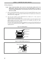
To adjust the position, insert the guide pins for position-adjustment (NQGUIDE) provided with
NQPACK144SD into the pin holes at the upper side of NQPACK144SD (refer to Figure C-1).
The diameter of a hole is
φ
= 1.0 mm. There are three non-through holes (refer to APPENDIX A
DIMENSIONS).
<3>
After setting the HQPACK144SD, solder NQPACK144SD to the target system. By following this
sequence, adherence of flux or solder sputtering to contact pins of the NQPACK144SD can be avoided.
Recommended soldering condition… Reflow
:
240
°
C, 20 sec. max.
Partial heating :
240
°
C, 10 sec. max. (per pin row)
<4>
Remove the guide pins.
Figure C-1. Mounting of NQPACK144SD
Remark
NQPACK144SD: Connector for target connection
HQPACK144SD: Cover for device installation
NQPACK144SD
Guide pins
(NQGUIDE)
HQPACK144SD
Target system
Содержание IE-703102-MC-EM1
Страница 2: ...2 MEMO ...
Страница 10: ...10 MEMO ...
Страница 24: ...24 MEMO ...
Страница 26: ...26 MEMO ...
Страница 34: ...34 MEMO ...
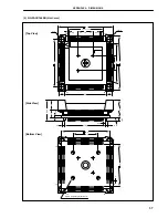
Страница 36: ...APPENDIX A DIMENSIONS 36 2 SC 144SD Unit mm 109 144 72 37 108 1 73 36 43 13 13 40 130 43 213 46 ...
Страница 40: ...40 MEMO ...
Страница 46: ...46 MEMO ...
Страница 48: ...48 MEMO ...


