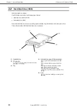
4. Names and Functions of Parts
Express5800/B120f User's Guide
28
Chapter 1 General Description
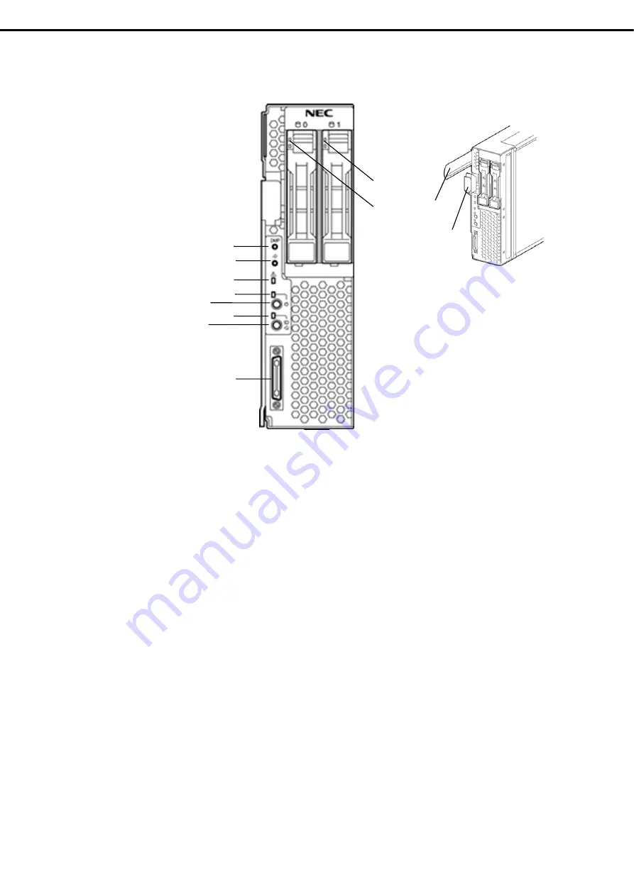
Front view
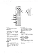
(1) DUMP
switch
Press this switch to collect memory dump.
(2) RESET
switch
Press this switch to reset the CPU blade.
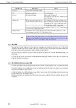
(3) STATUS LED (green / amber / red)
The LED indicates the status of the CPU blade.
See "LED Indications" for the indications and
meanings of the LED.
(4) POWER
LED
The LED goes on green when the CPU blade is
powered on.
The LED goes on amber when the CPU blade is
powered off but the power is supplied from the
power supply unit.
(5) POWER
switch
The switch is intended to turn on or off the power
of the CPU blade. Pressing the switch for four
seconds or longer causes the power supply to be
turned off forcibly.
(6) ID
LED
A LED for identifying the server.
The LED is lit when ID/BMC RESET switch is
pressed or command from NEC ESMPRO
Manager is received.
You can use the remote control feature of
EXPRESSSCOPE Engine 3 (BMC) to perform
the same operation as using the switch on the
server.
(7) ID/BMC
RESET
switch
Press this switch to turn on or off the ID LED.
Pressing the switch toggles LED ON/OFF.
Hold and press this switch to let it work as BMC
RESET switch. For BMC RESET switch, see
Chapter 1 (7.2 BMC Reset)
in Maintenance
Guide.
(8) SUV
connector
This connector sends or receives various signals.
The K410-150(00) SUV cable (separately-priced or
provided with the SIGMABLADE) is connected to
this connector.
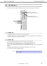
(9) Hard disk drive access LED #0
(Upper: green, Lower: amber)
(10) Hard disk drive access LED #1
(Upper: green, Lower: amber)
(11) Pull-out tag
A label on which the model number and serial
number are described is attached this tag. You can
check the label by pulling this tag.
(12) Eject lever
Pull the lever to remove the CPU blade from the
Blade Enclosure.
(1)
(2)
(3)
(4)
(5)
(6)
(7)
(8)
(10)
(9)
(12)
(11)

