background image

15

2. Operating the Projector Using the Touch Panel

2-6. LAMP Screen

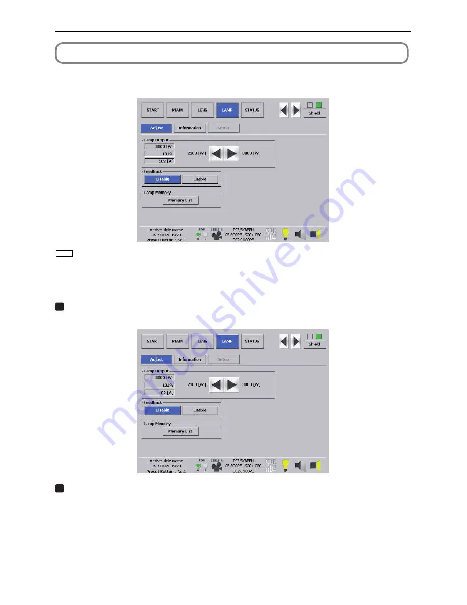
Press the [LAMP] button from the menu bar to go to the LAMP screen.

From the LAMP screen, you can adjust the lamp output and display the lamp information.

TIP

[Setup] button cannot be used (This button is used by the service personnel).

2-6-1. Adjusting the Lamp Output

1

Press the [Adjust] button from the LAMP screen.

The LAMP screen gets ready for adjustment.

2

Press the [

] / [

] buttons to adjust the output value.

Содержание DLP CINEMA NC1600C

Страница 1: ...eshooting 5 Service mode 6 Method of firmware upgrading 7 Adjustments and inspections attributable to the replacement of electrical and optical parts 8 Circuit description 9 Assembly diagram 10 Packaging 11 Replacement part list 12 Connection diagrams 13 Block diagrams 14 Replacement of the lamp house and bulb 15 Adjustments during prism assy replacement Back cover PART No 3N9911137 DLP Cinema Pro...

Страница 2: ...ons Ltd All Rights Reserved This document contains confidential information Unauthorized copying duplication distribution or republication is strictly prohibited 2 The contents of this manual are subject to change without prior notice ...

Страница 3: ... NC_data M10I MCGD data updating Interface Board 6 8 10 Common setting 6 9 10 1 Lamp off mode Remote controller operation 6 9 10 2 DLP Cinema Firmware Installation Program 6 10 10 3 DLP Cinema Control Program 6 11 10 4 Digital Cinema Communicator 6 13 ADJUSTMENTS AND INSPECTIONS ATTRIBUTABLE TO THE REPLACEMENT OF ELECTRICAL AND OPTICAL PARTS 7 1 Parts Replacement Work 7 1 Circuit Description 8 1 P...

Страница 4: ...CONTENTS 1 2 PACKAGING 10 1 REPLACEMENT PART LIST 11 1 CONNECTION DIAGRAMS 12 1 BLOCK DIAGRAMS 13 1 REPLACEMENT OF THE LAMP HOUSE AND BULB 14 1 ADJUSTMENTS DURING PRISM ASSY REPLACEMENT 15 1 ...

Страница 5: ...IN DE REDUIRE LES RISQUES D ELECTROCUTION NE PAS DEPOSER LE COUVERCLE IL N Y A AUCUNE PIECE UTILISABLE A L INTERIEUR DE CET APPAREIL NE CONFIER LES TRAVAUX D ENTRETIEN QU A UN PERSONNEL QUALIFIE Ce symbole a pour but de prévenir I utilisateur de la présence d une tension dangereuse non isolée se trouvant à l intérieur de l appareil Elle est d une intensité suffisante pour constituer un risque d él...

Страница 6: ...ge parts and if removed for servicing they must be retuned precisely to their original positions 5 LAMP Be very careful of the lamp because it generates high heat while it is used at high voltage When replacing the bulb make sure it is cool enough 6 LENS Do not look into the lens during projection This important to avoid damage to the eyes 7 SERVICING At the time of repair or inspection services u...

Страница 7: ...NC1600C User s Manual DLP Cinema Projector ...

Страница 8: ...is less than 70 dB A in accordance with EN ISO 7779 Disposing of your used product EU widelegislationasimplementedineachMember State requires that used electrical and electronic products carrying the mark left must be disposed of separately from normal household waste This includes projectors and their electrical accessories or lamps When you dispose of such products please follow the guidance of ...

Страница 9: ...connect to the connector for peripheral device wiring that might have excessive Voltage Remote Control Precautions Handle the remote control carefully If the remote control gets wet wipe it dry immediately Avoid excessive heat and humidity Do not heat take apart or throw batteries into fire If you will not be using the remote control for a long time remove the batteries Ensure that you have the ba...

Страница 10: ...NEC Europe Ltd European Technical Centre Address Unit G Stafford Park 12 Telford TF3 3BJ U K Telephone 44 1952 237000 Fax Line 44 1952 237006 In North America NEC Corporation of America Digital Cinema Division Address 4111 West Alameda Avenue Suite 412 Burbank CA 91505 Telephone 818 557 2500 If the above line is busy please dial as below Telephone 866 632 6431 Important Information ...

Страница 11: ... the title of input signal 23 3 4 Adjusting the position and the size of projected screen 24 3 5 Turning on off the lamp with the projector turned on 26 3 6 Turning your projector off 27 4 Using Menus 28 4 1 Basic operation with adjustment menus 28 4 2 Table of adjustment menus 32 4 3 Title Select 33 4 4 Configuration 34 4 5 Title Setup 34 4 6 Information 35 5 Maintenance of Your Projector 38 5 1 ...

Страница 12: ...y brightness setting from low brightness to high brightness This function makes it possible to minimize the fluctuation in brightness as brightness of the lamp decreases as a result of long term lamp usage The time for maintaining fluctuations in brightness depends on the setting value for brightness 3 Easy lamp replacement The lamp can be replaced from the backside of the projector so the lamp ca...

Страница 13: ...jector supports CineLinkTM CineCanvasTM CinePalletteTM and CineBlackTM which are the new functions for security subtitles etc developed by Texas Instruments Incorporated 1 CineLinkTM Security management This function supports encryption of the local link between server and projector adds a watermark to enable the tracing of pirated films illegal copying and provides other functions 2 CineCanvasTM ...

Страница 14: ...t for lamp x 1 Exhaust outlet protective sheet x 1 Exhaust outlet protective sheet fastening band x 4 Small iris x 1 Lamp door key x 2 Sheet of title labels for 20 labels x 2 Important Information x1 CD ROM User s Manual TIP In the event that you did not receive all of the accessories outlined above or some are damaged contact your dealer distributor Differs slightly from the drawings in this manu...

Страница 15: ...alling an optional multi media switcher MMS 4 Main power switch While AC power is being supplied set the main power switch to ON then your projector will enter a standby state 5 Touch panel mounting opening four position on top Use the holder arm for the touch panel to attach the touch panel optional 6 Lens optional Images are projected from the lens Request your dealer distributor to install or r...

Страница 16: ...ector Do not cover the air inlet 4 Lamp door This opens to allow the lamp to be replaced Please contact your dealer distributor to install and to replace the lamp bulb and lamp house 5 Rear status indicator These indicate the status of the projector When the projector is operating normally these light blink in green or orange When an error occurs they light blink in red When an error occurs check ...

Страница 17: ...Remote control input terminal REMOTE IN Stereo mini Connect the remote control of the projector using the supplied remote control cable Memo The projector s remote control can be used by connecting with the remote control cable See page 16 7 PC control signal switch CINEMA SYSTEM Use this to set data on the projector 8 PC control terminal RS 232C D Sub 9P This is used when the service personnel se...

Страница 18: ...reen The liquid crystal display screen shows menus and setting values for the operation of your projector 5 POWER button Press this button to turn on or off standby the power to your projector Press this for more than three seconds When turning on the power to the projector first set the main power switch to the main unit to ON thereby setting the projector in a standby state See page 21 6 POWER i...

Страница 19: ...essing the CTL LAMP button See page 26 13 MENU button Press this button and menus for various settings and adjustments will be displayed See page 29 14 MENU CTL UP DOWN LEFT RIGHT buttons Press the MENU CTL UP DOWN LEFT RIGHT buttons when the menu is displayed to select menu items 15 CANCEL button Press the CANCEL button to return to previous menu item 16 ENTER button Press the ENTER button and th...

Страница 20: ...n while depressing the CTL button then the green G signal of the test pattern will be turned off temporarily Press this button again while depressing the CTL button and the green G signal will be projected again 7 ENTRYLIST B button Press the ENTRYLIST B button while depressing the CTL button then the blue B signal of the test pattern will be turned off temporarily Press this button again while de...

Страница 21: ...er turning ON the back light switch the back light switch will automatically extinguish itself Thereafter it will light again when the remote control buttons are operated When using the remote control connected to the remote control cable The back light will constantly light when the power to the projector is turned on and when the projector is in standby status NOTE The following buttons cannot b...

Страница 22: ...ARD USB CINEMA SYSTEM Notes for use of the remote control Do not drop or handle the remote control in a careless manner Do not allow the remote control to be splashed with water or any other liquid If the remote control should get wet accidentally wipe the liquid off immediately Be sure to use the remote control in a place free from heat or dampness as far as is practicable The remote cable is con...

Страница 23: ...ps for setting up your projector Step 1 Setup the screen and projector Contact your dealer to carry out the setup Step 2 Connect cables to the image input terminals See page 18 Connect cables to the various control terminals See page 19 2 Installation and Connection ...

Страница 24: ...nput terminal the DVI D A input terminal and the DVI D B input terminal HDSDI A B input terminal SDI A SDI B Inputs serial digital images from a Video Server or Video source DVI D A B input terminal DVI A DVI B Inputs digital RGB signals from a PC SDI A SDI B DVI A DVI B GPI O LAN A LAN B REMOTE IN RS 232C PCCARD USB CINEMA SYSTEM 75Ω coaxial cable DVI D signal cable ...

Страница 25: ...inal and the Ethernet port RJ 45 PC control terminal PC CONTROL Use this terminal when controlling the projector in serial connection from a PC Ethernet port LAN 1 LAN 2 Use this port when controlling the projector in LAN connection from a PC SDI A SDI B DVI A DVI B GPI O LAN A LAN B REMOTE IN RS 232C PCCARD USB CINEMA SYSTEM RS 232C Ethernet cable ...

Страница 26: ... power to the projector See page 21 Step 2 Select the title of input signal See page 23 Step 3 Adjust the position and size of the projected screen See page 24 Step 4 Turn off the power to the projector See page 27 3 Projection of Images Basic Operation ...

Страница 27: ... remote control Turning power on See this page 1 Turn the main power switch on the projector head to on Your projector is set in a standby state 2 Press the POWER button POWER ON button on the remote control three seconds or longer Your projector is turn on Turning power off See page 27 1 Press the POWER button POWER OFF button on the remote control three seconds or longer Your projector is set in...

Страница 28: ...dup In the following instances the power to your projector cannot be turned on even if you press the POWER button When the inside temperature is abnormally high The protective function prevents power from turning on Wait some time until the projector inside cools down and then turn on the power When the STATUS indicator is blinking without the lamp lighting up after power on Your projector may be ...

Страница 29: ...tton 3 Press the MENU CTL LEFT RIGHT button to display Title Select on the LCD screen At each press of the MENU CTL LEFT RIGHT buttons the display will cycle as Title Select Configuration Title Setup Information 4 Press the MENU CTL DOWN button The title of the input signal is displayed When you have made a wrong selection press the MENU CTL UP button A return will be made to the previous menu 5 P...

Страница 30: ...rn is set 2 Press the SELECT button The display of the test pattern name on the LCD switches 3 Display on the LCD the name of the test pattern to be projected then press the ENTER button The test pattern is displayed To cancel the test pattern display reselect the signal to be project 3 4 2 Adjusting the position of the projected screen Lens shift 1 Press the LENS CTL UP DOWN LEFT RIGHT buttons wh...

Страница 31: ...tton while depressing the CTL LENS button 3 4 4 Focusing the projected screen Focus 1 Press the FOCUS buttons while depressing the CTL LENS button on the control panel of your projector as required When controlling with the remote control press the FOCUS button while depressing the CTL LENS button 3 4 5 Adjusting the brightness of the projected screen Lamp output 1 Press the LAMP buttons while dep...

Страница 32: ...urned on 3 5 1 Turning off the lamp 1 Press the LAMP OFF button while depressing the CTL LAMP button on the control panel of your projector as required 3 5 2 Turning on the lamp 1 Press the LAMP ON button while depressing the CTL LAMP button on the control panel of your projector as required ...

Страница 33: ... ended the POWER indicator and the rear STATUS indicator light in orange Standby When controlling with the remote control press the POWER OFF button for three seconds or longer 2 When the projector has entered the standby state turn the main power switch on the projector head to off The projector POWER indicator will extinguish and the main power will turn off 3 Turn off the AC power to the projec...

Страница 34: ...ed menus The meanings of symbols in the menu display screen are outlined below Indicates that there is a menu of a higher level Press the MENU CTL UP button to return to a menu one level above Indicates that there is a selected item or menu at the same level Press the MENU CTL LEFT RIGHT button to display other selected items or menus Indicates that there is a menu of a lower level Press the MENU ...

Страница 35: ... selected title Displays the selected port When the power is turned off The amount of time remaining for cooling is displayed as shown below when the power to the projector head is turned off 4 1 2 Operating menus Preparation Turn your projector on See page 21 1 Press the MENU button on the control panel of your projector The menu is displayed in the LCD screen 2 Press the MENU CTL LEFT RIGHT butt...

Страница 36: ...ycle as Lamp Macro Key Usage Error Code Version IP Address MMS Status 5 Press the MENU CTL DOWN button The submenu System another rank lower than Version is displayed 6 Press the MENU CTL DOWN button The submenu BIOS another rank lower than System is displayed 7 Press the MENU CTL LEFT RIGHT button to select the submenu Data At each press of the MENU CTL LEFT RIGHT button the display will cycle as...

Страница 37: ...ton while depressing the CTL button Example of Entry Numeric button 1 2 3 4 5 6 7 8 9 0 Press directly A B C 1 D E F 2 G H I 3 J K L 4 M N O 5 P Q R 6 S T U 7 V W X 8 Y Z 9 0 While depressing CTL button a b c d e f î g h i j k l m n o p q r s t u í v w x y z _ To enter XGA for example use the following procedure 1 Press the 8 button three times V W X 2 Press the SELECT button 3 Press the 3 button ...

Страница 38: ...itcher MMS to connect Sets the PC control connector RS 232C data transmission speed bps Sets the date and time on the projector Resets the lamp bulb usage time and selects or edits new entries only when the projector is in standby mode Sets the lamp bulb warning time only when the projector is in standby mode Resets the lamp house usage time and makes settings or selects modes only when the projec...

Страница 39: ...nd call them up directly using those buttons Request your dealer distributor for details on registering and changing titles Displays the currently selected item with asterisk Selects the title to be projected 4 3 2 Test Pattern Selects the test pattern to be projected OFF Alignment Cross Hatch Convergence Red Green Blue White Black White 50 IRE H Ramp Logo Displays the currently selected item with...

Страница 40: ...th regard to the setting Adjusts the lamp brightness Feedback Sets the lamp brightness constant mode that uses a brightness sensor Disable Enable Disables the lamp brightness constant mode Enables the lamp brightness constant mode Displays the currently selected item with asterisk Displays the setting 4 5 Title Setup Sets the titles to be assigned to the macro keys Request your dealer distributor ...

Страница 41: ...s Bulb Entry maximum minimum currents A Bulb Type W Displays the registered name and the lamp rated output kW of the currently used lamp bulb Displays Bulb Entry registered name Displays Bulb Entry lamp rated output kW Bulb Type H Displays the registered name and the lamp bulb warning time Bulb Warning Time and setting of the currently used lamp bulb Displays Bulb Entry registered name Displays Bu...

Страница 42: ...splay Displays the hours of use H 4 6 4 Error Code Displays the error code when an error occurs See the Error Code List in the Appendix for details on error codes Displays the code of the error currently occurring Displays the name of the error currently occurring When multiple errors occur you can display them by pressing the MENU CTL LEFT RIGHT buttons 4 6 5 Version Displays the versions of the ...

Страница 43: ... item to display Displays the version information 4 6 6 IP Address Displays the IP address set in the projector head System Cinema PC Card Displays the IP address set for the projector head System Displays the IP address set for the projector head Cinema To display the IP address when a wireless LAN card is set Selects the item to display the IP address Displays the IP address 4 6 7 MMS Status Ind...

Страница 44: ...r allow the cleaner without an adapter to come into direct contact or use a nozzles adapter in cleaning Clean the ventilation opening at regular intervals Dust if allowed to accumulate there may cause heating inside which leads to functional trouble The interval which can vary with the location of your projector is about 100 hours Do not damage the cabinet by scratching it or allowing hard objects...

Страница 45: ...e inside temperature is too high the protective function does not allow your projector to be turned on Wait some time and then turn it on Check to see if the connected input has been selected Check to see if a cable is properly connected to the input terminal Check to see whether the douser is closed Check to see if the settings are all adjusted properly Check to see if the protractor is properly ...

Страница 46: ...still good Replace with new batteries Check whether there is any obstructing object between the remote control and the light reception unit on the projector Check whether you are outside of the remote control s effective range 7m Check whether the remote control cable has become disconnected if you are using the remote control by connecting with the remote control cable Your projector may have tro...

Страница 47: ...ed on The projector is in standby Note Wait for a moment Wait for a moment Green Orange Green Orange 6 2 2 STATUS indicator Indicator condition Off Blinking light Red Projector condition Normal Error Note An error message is displayed in the LCD screen Check the content of the error 6 2 3 MMS STATUS indicator Indicator condition Off Blinking light Steady light Projector condition Multi media switc...

Страница 48: ...oblem error Error with possible image project under certain conditions The projector is turned on The projector is in standby Error at a level with not affect on projection Note Wait for a moment Wait for a moment An error message is displayed in the LCD screen Check the content of the error An error message is displayed in the LCD screen Check the content of the error Green Orange Red With buzzer...

Страница 49: ...Invalid IB FPGA INITZ Fail IB FPGA No Load Set IB FPGA DONE Fail IB FPGA Reg R W Fail IB Framestore Test Fail IB ANC FIFO Test Fail IB RTC Serial Fail IB UART0 Fail IB UART1 Fail IB IIC Fail IB Ethernet Fail IB Sync Serial Fail IB File System Fail IB Formatter Fail IB Flash Protect Fail IB GPI Macro Fail IB A D Macro Fail PB Diag Not Performed PB FPGA Code Invalid PB FPGA INITZ Fail PB McBSP XRDY ...

Страница 50: ...me LPSU Fail MMS Comm Fail MMS Fan Stop MMS Fail Fan0 Stop Fan8 Stop GPSU Fan Stop AC Fan Stop OverTemp Out OverTemp In OverTemp Chest OverTemp DMD Desctiption Lamp bulb cumulative time is over Lamp power supply is abnormal Built in MMS communication error is detected Built in MMS fan has stopped Error occurred inside built in MMS Fan has stopped Fan has stopped Fan has stopped Set inside temperat...

Страница 51: ...efore engaging in browser operations Operations with a browser that uses a proxy server may not be possible depending on the type of proxy server and the setting method Although the type of proxy server will be a factor it is possible that items that have actually been set will not be displayed depending on the effectiveness of the cache and the contents set from a browser not be reflected in oper...

Страница 52: ...stopped by clicking the same button one more time Zooms up the lens Zooms down the lens Stops the zooming Zooming the can also be stopped by clicking the same button one more time Focuses up the lens Focuses down the lens Stops the focusing Focusing can also be stopped by clicking the same button one more time Click and the douser closes and the projected picture disappears Click once again and th...

Страница 53: ...47 6 Appendix 6 5 Outline Drawing 700 503 360 990 Units mm ...

Страница 54: ...udes dust filter Less than 63 dB Orientation Desktop front Desktop rear 700 mm W x 990 mm D x 503 mm H Does not include protruding portions Includes foot 99 kg Excluding lens Operating temperature 5 to 35 C Operating humidity 10 to 85 non condensing Storage temperature 10 to 50 C Storage humidity 10 to 85 non condensing Safety EMC USA UL60950 1 FCC Class A Canada CSA60950 1 ICES 003 Class A Europe...

Страница 55: ...g indicator Projector Connector Operation Not used N C Data transmission to an external device Data reception from an external device Connection to 6 pins Signal GND Connection to 4 pins SYSTEM Note 2 Hi Z Not used CINEMA Note 2 Hi Z Used SYSTEM Note 2 Fixed at 6 5 V Not used CINEMA Note 2 10 5 V Used Depends on communication status Not used N C Note 1 Do not use DTR and DSR signals when communica...

Страница 56: ...pply unit and GND unit such as the projector head should short the protective function inside the projector will activate to prevent the shorted cable from damaging the projector 6 7 3 LAN port LAN A LAN B RJ 45 Use Ethernet 10Base T 100Base TX UTP Unshielded Twist Pair cable to connect with a video server or a PC A switching hub exists inside so there are no functional differences of either the L...

Страница 57: ..._P Ext_GPIN_7_P Ext_GPIN_8_P Ext_GPOUT_1_P Ext_GPOUT_2_P Ext_GPOUT_3_P Ext_GPOUT_4_P Ext_GPOUT_5_P Ext_GPOUT_6_P Ext_GPOUT_7_P Ext_PROJ_GOOD_P NC Reserve Reserve I O Input Input Input Input Input Input Input Input Output Output Output Output Output Output Output Output Pin No 20 21 22 23 24 25 26 27 28 29 30 31 32 33 34 35 36 37 Signal Name Ext_GPIN_1_N Ext_GPIN_2_N Ext_GPIN_3_N Ext_GPIN_4_N Ext_G...

Страница 58: ...N 4 23 OFF ON OFF ON OFF ON OFF ON 3 22 ON ON ON ON ON ON ON ON Photo coupler ON OFF ON ON Function Lamp on Lamp off Image doused Image un doused Selects title registered to MACRO 1 Selects title registered to MACRO 2 Selects title registered to MACRO 3 Selects title registered to MACRO 4 Selects title registered to MACRO 5 Selects title registered to MACRO 6 Selects title registered to MACRO 7 Se...

Страница 59: ...Macro off on off on Example of Select Macro approx 200 ms Off at least 500 ms at least 500 ms approx 200 ms 4 23 5 24 3 22 time Execute Image doused un doused off off on on Example of Image doused un doused Off at least 500 ms at least 500 ms approx 200 ms 1 20 2 21 time Execute Lamp On Off off on Example of Lamp On Off ...

Страница 60: ...x Output Connector GP I O Connector Inside Projector Photo coupler Ext_GPOUT_P Ext_PROJ_GOOD_P Pin No 9 10 11 12 13 14 15 16 Ext_GPOUT_N Ext_PROJ_GOOD_N Pin No 28 29 30 31 32 33 34 35 Absolute Maximum Rating 50 mA ...

Страница 61: ...pliant with hot plug detect HPD Use a single link cable Noise may be generated in the video if you use a dual link cable EDID is available even when the projector is switched off Pin No 1 2 3 4 5 6 7 8 9 10 11 12 Signal Name TMDS Data 2 TMDS Data 2 TMDS Data 2 Shield Unused Unused DDC Clock DDC Data Unused TMDS Data 1 TMDS Data 1 TMDS Data 1 Shield Unused Pin No 13 14 15 16 17 18 19 20 21 22 23 24...

Страница 62: ...1 75 to 2 4 1 Zoom Lens 2 4 to 3 9 1 Anamorphic lens 1 25 Anamorphic turret 4 0kW Lamp 4 0kW Lamp Long life type Power Cable kit Pedestal Wireless LAN Card NWL 100 Series Touch Panel Controler Touch Panel Holder Arm Air Filter Built in type Multi Media Switcher DVI Input Board SDI Input Board Analog RGB Input Board VIDEO Input Board Model name NC 60LS13Z NC 60LS17Z NC 60LS24Z AL 1 25 NC AT02 NC 16...

Страница 63: ... NEC Display Solutions Ltd 2007 Ver 2 07 07 ...

Страница 64: ...NC TP6402 NC TP6401 User s Manual Touch Panel Controller NEC Viewtechnology Ltd ...

Страница 65: ...measures CAUTION In order to reduce any interference with radio and television reception use a signal cable with ferrite core attached Use of signal cables without a ferrite core attached may cause interference with radio and television reception This equipment has been tested and found to comply with the limits for a Class A digital device pursuant to Part 15 of the FCC Rules These limits are des...

Страница 66: ...e doctor immediately This machine is designed to monitor and control the projector Do not use the machine for other than intended use Particularly never use this machine to make a device which may affect people s lives such as an emergency stop switch To prevent mis operation observe the following precautions Do not cut the power to the touch panel while the projector head is running When performi...

Страница 67: ...ire NC TH6403 pour le RU Au RU un cordon d alimentation approuvé par BS avec prise moulée est équipé d un fusible Noir 5A pour l utilisation avec cet équipement Si un cordon d alimentation n est pas fourni avec cet équipement veuillez contacter votre revendeur Mesures de sécurité importantes Ces instructions de sécurité garantissent la longévité de votre panneau de commande tactile et préviennent ...

Страница 68: ...qu un fil ou un tournevis à l intérieur de votre panneau tactile Si un objet tombe à l intérieur du panneau tactile débranchez immédiatement ce dernier et demandez à un technicien qualifié de retirer l objet Mise au rebut du produit usagé La législation européenne appliquée dans tous les Etats membres exige que les produits électriques et électroniques portant la marque à gauche doivent être mis a...

Страница 69: ...lgerät der Klasse B entspricht sämtlichen Anforderungen der kanadischen Regelungen für Funkstrahl Geräte Canadian Interference Causing Equipment Regulations Maschinenlärminformations Verordnung 3 GPSGV Der höchste Schalldruckpegel beträgt 70dB A oder weniger gemäß EN ISO 7779 Wechselstrom Netzkabel Zubehör des NC TH6403 für Großbritannien In Großbritannien ist ein BS geprüftes Netzkabel mit einem ...

Страница 70: ...enen Geräte den Strom ab Vorkehrungen gegen Feuer und elektrische Schläge Achten Sie darauf dass keinerlei fremden Gegenstände wie beispielsweise Büroklammern oder Papierschnipsel in Ihr Touchpanel geraten Versuchen Sie nicht in das Touchpanel hineingeratene Gegenstände zu beseitigen Führen Sie keinerlei Metallgegenstände wie beispielsweise einen Draht oder einen Schraubendreher in das Touchpanel ...

Страница 71: ...G 3 MEMO Important Information ...

Страница 72: ...the Touch Panel Sections 3 2 Operating the Projector Using the Touch Panel 5 2 1 Overview of the Touch Panel 5 2 2 Menu List 8 2 3 START Screen 9 2 4 MAIN Screen 11 2 5 LENS Screen 13 2 6 LAMP Screen 15 2 7 STATUS Screen 17 2 8 Other Menus 18 3 Appendix 19 3 1 Troubleshooting 19 3 2 Specifications 20 3 3 Appearance 22 1 ...

Страница 73: ... name NC TP6401 NC TP6402 Supports RoHS NC TP6402 Supports RoHS Your projector NC2500 NC1500 series NC800 series The following outlines accessories of the holder arm optional Accessory Holder arm For NC TH6401 LAN cable DC power cable Mounting screws 4 pcs Holder arm For NC TH6402 LAN cable DC power cable Mounting screws 4 pcs Holder arm For NC TH6403 LAN cable AC power cable Mounting screws 4 pcs...

Страница 74: ...ctor External control terminal RS 232C 422 485 This is not used with this controller External control terminal RS 232C This is not used with this controller DC IN terminal DC power input A power terminal Ask the service personnel to connect the power cable Power ON OFF switch The main power switch of this controller The power of the controller is linked with the power for the projector Use while t...

Страница 75: ...ct the controller with the projector Reset button This is not used with this controller External control terminal RS 232C This is not used with this controller DC IN terminal DC power input terminal A power terminal Ask the service personnel to connect the power cable Holder arm mounting hole Mount the controller to the projector using a bracket and these holes Power ON OFF switch The main power s...

Страница 76: ...the applicable on screen buttons by the finger This chapter explains the basic menu operations For details of the menus refer to Menu List See Page 8 2 1 1 Description of the Sections in the Menu Screen The menu screen of this controller consists of three sections below The selected active button is displayed in blue Menu bar Status bar Main window 2 Operating the Projector Using the Touch Panel ...

Страница 77: ...he status of the projector The projector is operating normally The projector is experiencing and error Lights Green Lights Red Main window The menu selected from the menu bar is displayed here Status bar The status of the controller is displayed with icons 1 2 3 4 5 6 7 8 1 Title Display Displays the selected title name and preset button number Displays title name Displays preset button number 2 S...

Страница 78: ...ed ON When the subtitle is turned OFF red white 6 Lamp icon Shows the status of the lamp ON OFF Lamp ON Lamp OFF yellow black 7 Anamorphic Lens Icon Shows the anamorphic lens In Out Using the anamorphic lens in Not using the anamorphic lens out red gray 8 Douser icon Displays the status of the douser open closed Douser is open Douser is closed yellow black 2 1 2 Inputting Alphanumeric Characters T...

Страница 79: ... lamp settings and call the saved settings To display the lamp information To set the lamp data Projector setting status is displayed in this screen Set titles and display the list in this screen This is used by the service personnel Screen for display of various information about the projector Screen for initial setting upon installation This is used by the service personnel Screen for LAN settin...

Страница 80: ...h the NC800 series check that the touch panel and AC power adapter are connected 1 Turn on the main power switch of the lamp power unit NC2500 series only 2 Turn on the main power switch of the projector If using a NC2500 NC1500 series projector the power to the touch panel will turn on by turning on the main power switch standby to the projector head If using a NC800 series projector the power to...

Страница 81: ...ending process is executed 4 When the projector head has entered the standby state turn the main power switch on the projector to off If you are using the projector head with the NC2500 NC1500 series the touch panel screen is cleared and the main power for the projector is turned off If you are using the projector head with the NC800 series turn off the power to the AC power adapter for the touch ...

Страница 82: ...Anamorphic lens control Anamorphic Out In button is unavailable 2 4 1 Selecting the Title of Input Signal Preset Button Display When you press Preset button on the MAIN screen titles registered to the preset buttons 1 to 8 are displayed Select the title of the input signal to be projected from the title list Note that the preset buttons 1 to 8 correspond to macro keys 1 to 8 on the projector Reque...

Страница 83: ... to the projector is displayed Select the title of the input signal to be projected from the title list Request your dealer distributor for details on registering and changing titles 2 4 3 Selecting the Test Pattern When you press Test on the MAIN screen a list of test patterns is displayed Selects the test pattern to be projected from the list of test patterns ...

Страница 84: ...he projection position downward 왗 button To move the projection position to the left 왘 button To move the projection position to the right STOP button To stop the lens shifting Press the 왖 왔 왗 or 왘 buttons again during moving to stop the moving Press the Fine adjust Mode button for fine adjustment 2 5 2 Finely Adjusting the Projection Screen Size Zoom Zoom in and zoom out the projection screen Zoo...

Страница 85: ...e lens memory it is not necessary to readjust lens shift zoom and focus for each work Lens Memory Press the Memory List on the LENS window to display the Lens Memory window Saves the current adjustment value to the memory Deletes the memory selected in the list from the Lens Memory Tests the adjustment value of the memory selected in the list Copies the memory selected in the list Saves the copied...

Страница 86: ...From the LAMP screen you can adjust the lamp output and display the lamp information TIP Setup button cannot be used This button is used by the service personnel 2 6 1 Adjusting the Lamp Output 1 Press the Adjust button from the LAMP screen The LAMP screen gets ready for adjustment 2 Press the 왗 왘 buttons to adjust the output value ...

Страница 87: ...ted in the list from the Lamp Memory Tests the adjustment value of the memory selected in the list Copies the memory selected in the list Saves the copied memory to any location Closes the Lamp Memory window and returns to the LENS window Entry button Delete button Test button Copy button Paste button OK button 2 6 3 Displaying Lamp Information Press the Information button in the LAMP screen to di...

Страница 88: ...rating the Projector Using the Touch Panel 2 7 STATUS Screen Press the STATUS button from the menu bar to display the STATUS screen From the STATUS screen you can display various setting status of the projector ...

Страница 89: ...you press Error Log an error log information screen is displayed When you press System Log a system log information screen is displayed SETUP Screen used by the service personnel This is not available in regular operation Used when making default settings at setup LAN Screen used by the service personnel This is not available in regular operation Used when making LAN settings of SYSTEM and CINEMA ...

Страница 90: ...ower switch of the touch panel is set to ON Is the power cable disconnected from the DC IN terminal on the touch panel When the projector head is the NC800 series Is the AC power cable disconnected from the AC power cable Check if the screen is not contaminated Is the LAN cable that connects the touch panel to the projector head disconnected Check if the shield button is set to ON Phenomenon Power...

Страница 91: ...o 85 No dewing is allowed DC12 24V When DC power cable is used AC100 V 50 60Hz When AC adapter is used 36W 3 0A Max 218 width x 151 height x 74 2 length mm not including protrusions and a holder arm 1 8kg NC TP6401 4096 colors LAN port RJ 45 USB port Type A DC 19 24V 48W 2 0A Max 220 width x 190 height x 47 8 length mm not including protrusions and a holder arm 1 4kg Model Number LCD panel OS Inpu...

Страница 92: ...ted input current Dimensions externes Poids Type de panneau Taille de l écran Points de l affichage Couleurs de l affichage Technische Daten NC TP6402 TFT Farb LCD Hintergrundbeleuchtung 6 4 Zoll VGA 640 H x 480 B 262 000 Farben Microsoft Windows CE LAN Port RJ 45 USB Port Typ A PS 2 Tastatur Maus Port RS 232C Port RS 232C 422 485 Port VGA Port Betriebstemperatur 5 bis 35 C Betriebsluftfeuchtigkei...

Страница 93: ...NC TP6402 218 151 187 74 2 53 120 unit mm The dimensions above do not include protrusions and the holder arm 3 3 2 NC TP6401 190 220 135 23 187 25 16 87 26 3 47 8 unit mm The dimensions above do not include protrusions and the holder arm ...

Страница 94: ... NEC Viewtechnology Ltd 2005 2006 Printed in Japan Ver 2 06 06 ...

Страница 95: ...7N8P6692 Printed on recycled paper NC TP6402 NC TP6401 User s Manual ...

Страница 96: ...ke Check POSTA of the PJDIV PWB This is the connector that must be disconnected without fail when the top panel is removed at the time of the installation If the power supply is not turned on even when the connector is pulled out check the POSTA connector pin of the PJDIV PWB If it is found broken replace the PJDIV PWB If the connector is pulled out and the power supply is turned on check the POST...

Страница 97: ... at the remote control No Yes If this error seems to occur repeatedly replace the EFIB PWB etc Are no pictures displayed at both optional MM2000B input and main unit side input Yes No Are pictures displayed at main unit side input Yes No To MM2000B error check MOTHER PWB or DVI OUT PWB is faulty Are the specified voltages available at TP8005 TP8004 and TP8003 of the PJDIV PWB Yes Adjust the VR of ...

Страница 98: ... Confidential Do Not Duplicate without written authorization from NEC 4 3 TROUBLESHOOTING Specified values TP8005 3 40 0 05 VDC TP8004 5 10 0 1 0 0 VDC TP8003 12 00 0 1 VDC ...

Страница 99: ...emote control and its cable Is it possible to adjust FOCUS and ZOOM Yes No Check the LENS connector Are the connectors of POJ100 and POSIO correctly inserted in the PJDIV PWB Yes No Try to insert the corresponding connectors again Is the power 12V supplied to POJ100 3 and 4 of the PJDIV PWB Yes No Check 12V of the DIV PWB Is the power 3 3V supplied to POJ100 8 of the PJDIV PWB Yes No Check IC8001 ...

Страница 100: ...he build in MMS selected Yes No Select the build in MMS according to the menu Are connectors and cabling wrongly installed Yes No Correct the wrong installations if any Does operation still fail even though the software of the main unit side and MM2000B are updated Yes The MM2000B is faulty Refer to the MM2000B Service Manual ...

Страница 101: ... Confidential Do Not Duplicate without written authorization from NEC 4 6 TROUBLESHOOTING FAN 0 FAN 0 Lamp FAN Lamp FAN FAN 2 FAN 2 FAN 3 FAN 3 FAN 1 FAN 1 FAN 7 FAN 7 FAN 6 FAN 6 NC1600C FAN Location ...

Страница 102: ...nnected on the Cover PWB and PJDIV PWB sides Reinsertion of the connector Yes No Are POCOV 1 and 2 short circuited when the Cover PWB switch is pressed Do 1 and 2 maintain continuity on the Cover PWB and PJDIV PWB sides of POCOV Is it impossible to remove the fault even after the replacement of PJDIV PWB Check the connectors between the CPU PWB and PJDIV PWBs and replace the CPU PWB if there is no...

Страница 103: ...s No Is there no clogging in the air filter Replace the air filter Yes No Is ventilation normal when the power is ON Is the potential at 1 on the PJDIV PWB side of Cable TH maintained at the GND level Is it impossible to eliminate malfunction even after the replacement of the PJDIV PWB Check the connectors in the CPU PWB and between the CPU PWB and the PJDIV PWB Replace them as required Replace th...

Страница 104: ... Confidential Do Not Duplicate without written authorization from NEC 4 9 TROUBLESHOOTING House Over Time Replace the lamp reflector ...

Страница 105: ... between the PJDIV PWB and the CPU PWB If any problem is discovered replace it No Yes For the fan where Connector 3 for a fan on the PJDIV PWB is not maintained at the GND level check whether 24V is applied to 1 Check for connector disconnections If there is no problem replace the fan Yes No Is 24V applied to POPN 1 on the PJDIV PWB Check the connector connections between the PJDIV PWB and the pow...

Страница 106: ... Confidential Do Not Duplicate without written authorization from NEC 4 11 TROUBLESHOOTING OutRange Lamp xx xxx xxx This is not an error Check the lamp output Replace the lamp bulb as required ...

Страница 107: ...evel Check for disconnections and breakage at POCF and POCE on the PJDIV PWB and the CPU PWB Replace them as required Yes No Is the potential at POPSC 5 on the PJDIV PWB maintained at the GND level Check connections of the AC PWB and the noise filter electrode screws loosened and examine the AC source voltage 200 240V Replace the power supply if there is no problem Replace the power supply ...

Страница 108: ...WB such as drawing out of the connector Adjust the problem points Yes No Is there any abnormality between the PJKEY PWB and the RELAY PWB such as drawing out of the connector Adjust the problem points Look for any damage or the drawing out of the connector and follow the steps of replacement work in the order specified below RELAY PWB PJDIV PWB Liquid cooling unit CPU PWB ...

Страница 109: ... after several seconds after the set has been powered ON Caution Never touch the HV terminal because a voltage of 35kV appears at that time Replace the lamp power supply No Yes Is the problem solved when the Lamp House is replaced Is the problem solved when the igniter is replaced End of repair service End of repair service No Yes Check the cabling materials that are relating to the lamp power sup...

Страница 110: ...o that the ambient temperature is below 35 C or equipment operating temperature upper limit No Yes Is there no clogging at the exhaust port Remove the clogging obstacle No Yes Is there no clogging in the air filter Replace the air filter Yes No Is ventilation normal when the power is ON Replace the lamp power supply Replace the related fan if there is any error such as fan stop ...

Страница 111: ...nector Adjust the faulty spots Yes No Is there any abnormality between the ETHER PWB and the MOTHER PWB such as drawing out of the LAN connector Adjust the faulty spots Adjust the faulty spots Yes No Is there any abnormality between the ETHER PWB and the PJDIV PWB such as drawing out of the connector Follow the steps of replacement work in the order specified below ETHER PWB PJDIV PWB CPU PWB INTE...

Страница 112: ...om NEC 4 17 TROUBLESHOOTING DLP CommR Fail Yes No Is there any abnormality between the CPU PWB and the MOTHER PWB such as drawing out of the connector Adjust the faulty spots Follow the steps of replacement work in the order specified below CPU PWB INTERFACE board ...

Страница 113: ...onnectors Yes No Is there any drawing out of the connector on the CPU PWB Reinsert the associated connector Yes No Are there no connector disconnections on the GPSU and no such abnormalities Reinsert the associated connector Yes No Is the GND potential available at POPSC 5 on the PJDIV PWB Replace the CPU PWB Replace the PJDIV PWB If repair servicing is still needed at this stage replace the GPSU ...

Страница 114: ...WB and the PJDIV PWB such as drawing out of the connector Adjust the problem points Yes No Is there any abnormality between the CPU PWB and the PJKEY PWB such as drawing out of the connector Adjust the problem points Look for any damage or the drawing out of the connector and follow the steps of replacement work in the order specified below PJDIV PWB PJKEY PWB CPU PWB ...

Страница 115: ...e associated connectors No No Are the TP voltages normal at the DIV PWB as specified below TP8005 Normal value 3 4V 0 05V TP8004 Normal value 5 05V 0 05V TP8003 Normal value 12 05V 0 05V Adjust the VR of GPSU to secure a normal value Replace the GPSU as required Follow the steps of replacement work in the order specified below PJDIV PWB CPU PWB GPSU Interface board ...

Страница 116: ... Confidential Do Not Duplicate without written authorization from NEC 4 21 TROUBLESHOOTING Bulb Over Time Replace the Lamp Bulb ...

Страница 117: ... Confidential Do Not Duplicate without written authorization from NEC 4 22 TROUBLESHOOTING Bulb Entry Set up the Lamp Bulb ...

Страница 118: ...he faulty spots Yes Yes Is the AC power supply available Check for breakage and connector disconnections in the sequential order as specified below and replace them as required AC input terminal board AC PWB Circuit breaker Noise filter Check for breakage and connector disconnections in the sequential order as specified below and replace them as required PEDE A PWB CPU PWB Lamp power supply ...

Страница 119: ...TING CPU Fail Mem CPU Fail IO C CPU Fail IO A Yes No Is there any abnormality between the CPU PWB and the PJDIV PWB such as drawing out of the connector Adjust the faulty spots Yes No Is it possible to solve the problem through NEC software rewriting Normal operation Replace the CPU PWB ...

Страница 120: ... Fail Yes No Is there no problem in external control There is occasionally interference with an external interlock Normal operation Look for any damage or the drawing out of the connector and follow the steps of replacement work in the order specified below Replace them as required PEDE A PWB CPU PWB ...

Страница 121: ... disconnections and breakage of the POPS or POPSM1 and POPSM3 on the PJDIV PWB Replace them as required Yes No Check for disconnections and breakage of the POPOJ100 and POSIO on the PJDIV PWB Adjust disconnections of the POPOJ100 and POSIO on the PJDIV PWB Replace them as required Replacement work shall be carried out in the sequential order as specified below PJDIV PWB MOTOR PWB CPU PWB ...

Страница 122: ...BLESHOOTING MMS Comm Fail MMS Fan Stop MMS Fail Yes No Is the Built in MMS selected by menu setting Select the Built in MMS Yes No Is there any fault in connections with the MMS such as disconnection or breakage Adjust the faulty spot MM2000B error Refer to MM2000B Service Manual ...

Страница 123: ...il Out Sensor Fail In Sensor Fail Chest Sensor Fail DMD Sensor Fail Rear Yes No Is there any abnormality between the PJDIV PWB and the TSENS PWB such as drawing out of the connector Adjust the problem points Follow the steps of replacement work in the order specified below TSENS PWB PJDIV PWB CPU PWB ...

Страница 124: ...il PB Resizer FIR Fail PB Resizer FIFO Fail PB Other Fail FB Red RDRAM Signature Fail FB Green RDRAM Signature Fail FB Blue RDRAM Signature Fail FIB Test Fail MF R Test Fail MF G Test Fail MF B Test Fail Yes No Is board fitting sufficient in the TI Chest Reinsert the associated connectors Yes No Are voltages of the PJDIV PWB maintained at the values specified below TP8005 Normal value 3 4V 0 05V T...

Страница 125: ... Confidential Do Not Duplicate without written authorization from NEC 4 30 TROUBLESHOOTING Invalidate Card LAN Review the setup conditions for the wired and wireless LAN Addresses shall be duplicated ...

Страница 126: ...djust the problem points Adjust the problem points Yes No Is there any abnormality in the lid of the TI Chest Yes No Is there any abnormality between the PJKEY PWB and the TAMPER PWB such as drawing out of the connector Look for any damage or the drawing out of the connector and follow the steps of replacement work in the order specified below TAMPER PWB PJDIV PWB CPU PWB INTERFACE Board ...

Страница 127: ...crews tightened Adjust the problem points Adjust the problem points Yes Yes No Is there any abnormality between the PJKEY PWB and the TAMPER PWB such as drawing out of the connector Look for any damage or the drawing out of the connector and follow the steps of replacement work in the order specified below TAMPER PWB PJDIV PWB CPU PWB ...

Страница 128: ... Power ON Lamp ON Stand By 20 sec 2000 msec Title setup Reset TI Circuit Enable Normal Operation Normal Operation High Picture Mute On Picture Mute Off Douser Open Turret Select High anamorph Low Non Supervision High Error Low Normal Supervision High Error Low Normal Supervision High Error Low Normal Supervision High Error Low Normal Supervision High Error Low Normal Supervision High Error Low Nor...

Страница 129: ...rmal Supervision High Error Low Normal Supervision High Error Low Normal Supervision High Error Low Normal Supervision High Error Low Normal TI Circuit Disable Disable Disable Disable Disable Disable Douser Close Control items Interlock supervision Power ON control POWER_BIT Lamp control TI circuit control POWER GOOD TI circuit control ResetZ Video mute control DOUSER control Anamorphic turret con...

Страница 130: ...Mute Off Picture Mute Off Picture Mute On Signal setting Douser Open Douser Open Douser Close Turret Slect A High anamorph Low Non Turret Slect B High anamorph Low Non Turret moving time max 25 sec Title A Title B Changeover period Control items Lamp control Video mute control DOUSER control Anamorphic turret control ANAMO BIT ...

Страница 131: ...nd press the ENTER key Macro Key Macro Key No 1 Title No 10 Title name 1Macro Key Selection of Title Memory registration Example of display Macro Key Macro Key No 1 Title No 10 Title name First line Indication of Macro Key Second line Indication of Macro Key number Macro Key Nos 1 8 Third line Indication of Title number 1 Indication of current setup Fourth line Indication of Title Name registered ...

Страница 132: ...tor operated turret of the anamorphic lens 1Manual The Mode to use the motor operated turret of the anamorphic lens without any linkage with the title Example of display Turret Manual Without Anamo First line Indication of Turret Second line Indication of Manual Third line Indication of current setup Fourth line For Enable Anamo used With Anamo For Disable Anamo not used Without Anamo 2Control The...

Страница 133: ...MM is disconnected or disconnection is required Example of display Setup Ext MMS Link Connect First line Indication of Setup Second line Indication of Ext MMS Link Third line Indication of current setup Fourth line For Enable Connect For Disable Disconnect 1 1 Linkage with the External MM is disconnected The status of disconnection is maintained until the next connection is made Panel Key Lock Ena...

Страница 134: ...y Example of display First line Indication of Factory Default Second line Indication of M Key Title Third line Void Fourth line Indication of Execute 2All The setting conditions are initialized Including Macro Key registration and Title The status of shipment from the factory is assumed However lamp setting and network setting are not initialized Factory Default M Key Title Execute Example of disp...

Страница 135: ... Normal Rear Normal R UpsideDown Front UpsideDown F 1 1 Enabled only for the NC800C Lens Calibrate When the Execute ENTER key is pressed positioning of the ZOOM and FOCUS lenses is carried out Example of display Installation Lens Center Execute First line Indication of Installation Second line Indication of Lens Center Third line Void Fourth line Indication of Execute Lens Center When the ENTER ke...

Страница 136: ...her operation will sometimes become slow because the projector itself tries to search for the multimedia switcher When no multimedia switcher is connected Not Use should be selected 1Use of built in MMS Example of display Installation MMS Select Built in 2 Use of externally connected MMS Example of display Installation MMS Select Exernal 3 MMS not in use Example of display Installation MMS Select ...

Страница 137: ...rd line Indication of current setup Fourth line Indication of communication speed 4 800 9 600 19 200 38 400 Date Time Projector s Date and Time are set up Date Year month day day of the week 1 05 07 11 Mon Move the cursor and enter numeral data through the tenkey Time 1 16 27 33 Move the cursor and enter numeral data through the tenkey 1Date setup Example of display Data Time Data 05 07 11 Mon Fir...

Страница 138: ... are newly carried out 1Bulb Entry selection Used when selecting the bulb type from the Bulb Entry already registered When a new bulb is selected confirmation of Air Filter replacement and lamp Usage clear is made in the screen Selection of a new bulb cannot be accomplished unless all items of UsageClear OK are OK Example of display New Bulb Entry Select Entry Name First line Indication of New Bul...

Страница 139: ...istered For new establishment Select a new Entry and enter the required input items When all input entry is finished move to a higher hierarchical level of the menu When returning to a higher menu a screen for entering the Entry Name is displayed Then enter the Entry Name Example of display New Bulb Entry Edit Entry Entry First line Indication of New Bulb Second line Indication of Entry Edit Third...

Страница 140: ...0 A Lamp Range 4 50 65 A c Typical Watt Setup indispensable in the case of New Entry Enter the typical wattage input of the Lamp Bulb If there is no Max Watt setup Typical Watt becomes the maximum wattage for lamp control Lamp control is effected within the range of 70 100 of Typical Watt Example of display Entry Name Typical Watt Max6 00 kW 6 00 kW First line Indication of Entry Name being edited...

Страница 141: ...of display Entry Name Max Watt Typ7 00 kW 6 00 kW First line Indication of Entry Name being edited Second line Indication of Max Watt Third line Indication of Typical Watt and Current setup Fourth line Indication of Wattage value Input 1 1 6 00 Enter numerical inputs by cursor movement Initial display is 0 00 It is necessary to enter Typical Watt in the first place Input range Typical Watt Max Wat...

Страница 142: ...ay Entry Name Warning Time 1000 H First line Indication of Entry Name being edited Second line Indication of Warning Time Third line Indication of current setup Fourth line Indication of Warning Time Input 1 1 1000 Enter numerical inputs by cursor movement Initial display is It is unnecessary to enter Warning Time input Indication at that time No warning is given in this case To set up no warning ...

Страница 143: ...Warning Use Blb Entry First line Indication of Installation Second line Indication of Bulb Warning Third line Indication of current setup Fourth line Indication of Use Bulb Entry 2Manual Warning Time for Manual setup is used Example of display Installation Bulb Warning Manual First line Indication of Installation Second line Indication of Bulb Warning Third line Indication of current setup Fourth ...

Страница 144: ...p House Usage Time is cleared to zero Multi mode Lamp House Usage Time for the selected House 1 or House 2 is cleared to zero Example of display New Lamp house Usage Clear House First line Indication of New Lamp House Second line Indication of Usage Clear Third line Indication of current setup Fourth line Indication of Lamp House to be cleared Single mode House Lamp 1 used in multi mode House 1 La...

Страница 145: ...e Multi Lamp house 1 First line Indication of Usage Mode Second line Indication of Multi Third line Indication of current setup Fourth line Indication of Lamp House Lamp 1 used in multi mode House 1 Lamp 2 used in multi mode House 2 3Usage Mode Single This function is selected when a single lamp house is used Example of display New Lamp house Usage Mode Single First line Indication of New Lamp Hou...

Страница 146: ...gnment Third line Indication of Peak Hold value Fourth line Indication of Average value Peak hold Maximum value read out by the optical sensor is displayed This value is cleared when ENTER is pressed Average A mean value of the data obtained by the optical sensor is displayed Memory The present status of Lamp and Lens is overwritten in Entries of the selected lamp and lens memories 1Lamp The prese...

Страница 147: ...tion of Overwrite Third line Indication of Yes No Fourth line Popup decoration 2Lens The present status of Lens output is overwritten in the selected Lens Memory Entry Example of display Memory Lmap Memory Name Popup Menu Example of display Lamp Memory Over Write Yes First line Indication of Lens Memory Second line Indication of Overwrite Third line Indication of Yes No Fourth line Popup decoratio...

Страница 148: ...date 1 1 Software Version Check and Update 3 Error Status Check 4 All Versions Check Interface Processor and FFIB Versions 5 All Firmware Updata 6 Cinema Board Update 7 FFIB Update 8 Reset All Versions Check Error Sys Status 9 NC_datav M10I MCGD writing Reg Batch Power Off Power Off Repair NG NG NG NG NG OK OK OK NG OK OK OK OK OK NG ...

Страница 149: ...r to 10 3 DLP Cinema Control Program 2 Select the Sys Status tab and check the status Disregard the failures of Self Test because they are automatically cleared at the time of updating If there is any error turn off the projector power supply once and confirm that the Interface Board the Processor Board the FFIB Board and the wiring cables between FFIB and FSB are certainly installed Caution If th...

Страница 150: ...re the release version of Current Projector Info with that of Selected Release and write the obtained data on the list to be specified separately If there is any discrepancy in versions of Current Projector Info and Selected Release update the discrepancy items according to the instructions specified below Discrepancy in all versions of Interface Board and Processor Board and FFIB Item 5 Discrepan...

Страница 151: ...Processor FFIB 1 Start DLP Cinema Firmware Installation Program from the PC for login Refer to 10 2 DLP Cinema Firmware Installation Program 2 Press and select Release dlpcinema from the folder where the firmware is stored Select Release Installation File Start Auto Install OK OK 5 Input ID and password specified below and press the button ID Service Password Heal Thyself for Blank 6 END upon the ...

Страница 152: ...r 1 Start DLP Cinema Firmware Installation Program from the PC for login Refer to 10 2 DLP Cinema Firmware Installation Program 2 Press and select Release dlpcinema Select Release Installation File Special Operations 3 Press Select Auto Install Cinema Boards Only and press 4 After the completion of updating check versions again OK ...

Страница 153: ...FFIB 1 Start DLP Cinema Control Program from the PC for login Refer to 10 3 DLP Cinema Control Program 2 Press and select Release dlpcinema Select Release Installation File Special Operations 3 Press Select Auto Install Formatter Subsystem Only and press 4 After the completion of updating check versions again OK ...

Страница 154: ...a Control Program 2 Select the Connection tab and press the button Reset Projector 3 Confirm the version 4 Select the Sys Status tab and confirm that there is no error or failure in the status Caution If there is any failure relating to Self Test after updating there lies a certain problem In this case an adequate measure has to be taken separately 5 After the completion of firmware data writing t...

Страница 155: ... ON the projector power supply 2 Start the Digital Cinema Communicator from the PC Mode in Service 3 Press the button of Restore from PC in the UPDATE menu A check mark is given to the In the case of installation after the replacement of an interface board Remove the check mark In cases other than the above Leave the check mark as it is Restore Skip MCGD File ...

Страница 156: ...e key 4 SOURCE PCF SCREEN TGA FILE MCGD FILE update Select the nc16_V FactoryC txt file Open CTL PIXEL ENTER 3 Turn the power supply ON from the remote controller or the key of the projector main body Caution The Lamp Off mode is canceled when the power supply is turned OFF To make the power supply turned ON again in the Lamp Off mode follow the steps of 1 to 3 above Press the button The nc16_V Fa...

Страница 157: ...r the PC network to the figures specified below IP Address 192 168 010 17 Gateway 192 168 010 17 Subnet Mask 255 255 255 0 1 Start DLP Cinema Firmware Installation Program from the PC Caution Use the version program attached to the latest release without fail 2 Setting for the projector being connected Enter the IP address of 192 168 10 11 Select Ethernet Port Enter IP Address 192 168 10 11 3 Sele...

Страница 158: ...ed in Current Projector Info is displayed 10 3 DLP Cinema Control Program Preliminary arrangements Not required if setting is already finished in the PC Make settings for the PC network to the figures specified below IP Address 192 168 010 17 Gateway 192 168 010 17 Subnet Mask 255 255 255 0 1 Start DLP Cinema Control Program from the PC Caution Use the version program attached to the latest releas...

Страница 159: ... of 192 168 10 11 3 Select the connecting port Select the External Ethernet port When connection is successful Log In is displayed in Version Info 4 Security setup Enter the User ID and Password in the Security item and press ID Service Password Heal Thyself for Blank When Log In is successful the version information specified below is displayed in Version Info Login ...

Страница 160: ... arrangements Not required if setting is already finished in the PC Make settings for the PC network to the figures specified below IP Address 192 168 010 17 Gateway 192 168 010 17 Subnet Mask 255 255 255 0 1 Start DigitalCinemaCommXP exe 2 Communication setup Select Communication Settings of Setup Enter the IP address of 192 168 10 10 and press OK ...

Страница 161: ...Confidential Do Not Duplicate without written authorization from NEC 6 14 METHOD OF FIRMWARE UPGRADING 3 Service mode setup Press at top right MODE Press the popup screen and enter 3151 Press Service OK ...

Страница 162: ..._pjdat folder of the compact flash memory In cases other than the above Copy Data is16vxxx_service bin into the _pjdat folder of the compact flash memory 3 Insert the Compact Flash memory in the PCCARD slot 2 Firmware updating Projector MENU CTL key operation 1 Turn the power switch ON while the key is kept pressed 2 When the Status LED is turned green press the key 3 Press the key 1 2 3 CANCEL CA...

Страница 163: ... 2 3 CANCEL CANCEL MENU POWER SW CANCEL CANCEL MENU LCD Display Data being updated End of data update Data Update Data Update Completed 4 Turn the power switch OFF and pull out the Compact Flash memory Caution Failure in updating Power LED blinking in red Retry updating After the completion of firmware and data updating let the projector to assume the Standby status According to Information Versio...

Страница 164: ... check Confirmation of image display 7 15 Picture quality check Item SDI A SDI B DVI A DVI B Any input acceptable GPIO 7 18 Operation check for external LAN TI control terminals Serial TI IInterface board MSN No writing Memo the numbers on boards Digital Certification 7 22 Digital Cinema Certificate Refer to data acquisition Adjust Item Version check for cinema software 5 Confirmation of cinema so...

Страница 165: ...g 7 22 Digital Cinema Certificate Digital Certification Refer to data acquisition Adjust Item Adjustment of GPSU output 4 Output adjustment for General Power Supply Unit PJDIV PWB Inspection Confirmation of image display 7 15 Picture quality check Confirmation of image display 7 15 Picture quality check Item Any input acceptable Any input acceptable Touch panel power supply 7 19 Operation check fo...

Страница 166: ...Item access to the CPU and TI circuit terminals 4 Ethernet terminal check terminals Operation enabled for the touch panel 7 19 Operation check for optional and MM2000B equipment Replacement of PJKEY PWB Items for Reference Replacement of GPSU Main PS Items for Reference Adjust Item Adjustment of GPSU output 4 Output adjustment for General Power Supply Unit PJDIV PWB Inspection Key operation enable...

Страница 167: ...SPECTIONS ATTRIBUTABLE TO THE REPLECEMENT OF ELECTRICAL AND OPTICAL PARTS Adjust item Inspection Confirmation of image display 7 15 Picture quality check Item Any input acceptable Touch panel power supply 7 19 Operation check for optional equipment Replacement of Standby PS Items for Referenc ...

Страница 168: ...LPARTS Software Version Check and Update Flow Cinema Software Check and Update Error Status Check All Versions Check Interface Processor and FFIB Versions All Firmware Updata Cinema Board Update FFIB Update Reset All Versions Check Error Sys Status NC_datav M10I MCGD writing Reg Batch Power Off Power Off Repair NG NG NG NG NG OK OK OK NG OK OK OK OK OK NG ...

Страница 169: ...FB 2 Change over the projector title to Macro Key 1 SDI A 3 Display the Ramp signals to confirm the freedom from gradation skip coloring and others 4 Display chart patterns and others to confirm the freedom from jitter coloring etc 5 Change the connection to the SDI B input terminal of the projector 6 Change over the projector title to Macro Key 2 SDI B and make confirmation for Items 3 to 4 3 3D ...

Страница 170: ... operation Refer to the table below Resetting shall be possible when the keys are pressed again POWER LED SCREEN DOUSER ON Blinking in green Not displayed DOUSER OFF Green Displayed 3 RS232C terminal check 1 CINEMA Make connections toward the PC through the RS 232C cable extension Straight Cable Let the CINEMA SYSTEM changeover Push Switch assume a protruded state Start the DLP Cinema Control Prog...

Страница 171: ...tor and confirm that the respective functions specified in the table below are available under the control from the GPIO tester On Off in the table below The On period shall be 500ms or more However operation check for the Lamp on off function is possible even in the middle of the projector in Standby mode In the standby mode the present Lamp on off status is displayed in the LCD screen The GPIO s...

Страница 172: ...or System IP Address and Cinema IP Address as specified below System IP Address 192 168 010 010 Cinema IP Address 192 168 010 011 Press and acquire data Execute 4 Acquisition of Data has been completed when Complete is displayed in the last line of the screen 5 The Data File is saved in the folder where the ReadCert exe is present with the File name expressed by the serial number of the Projector ...

Страница 173: ... Board exchange FFIB Board exchange Prism ASSY exchange Software Version Check and Update Flow Error Status Check All Versions Check Interface Processor and FFIB Versions All Firmware Updata Cinema Board Update FFIB Update Reset All Versions Check Error Sys Status NC_datav M10I MCGD writing Reg Batch Power Off Power Off Repair NG NG NG NG NG OK OK OK NG OK OK OK OK OK NG ...

Страница 174: ... FB 2 Change over the projector title to Macro Key 1 SDI A 3 Display the Ramp signals to confirm the freedom from gradation skip coloring and others 4 Display chart patterns and others to confirm the freedom from jitter coloring etc 5 Change the connection to the SDI B input terminal of the projector 6 Change over the projector title to Macro Key 2 SDI B and make confirmation for Items 3 to 4 3 3D...

Страница 175: ...r through a BNC cable 5C FB 2 Change over the projector title to Macro Key 1 SDI A 3 Display the Ramp signals to confirm the freedom from gradation skip coloring and others 4 Display chart patterns and others to confirm the freedom from jitter coloring etc 5 Change the connection to the SDI B input terminal of the projector 6 Change over the projector title to Macro Key 2 SDI B and make confirmati...

Страница 176: ...are Data Update 1 Preparation Copy the Firmware and Data file in the Compact Flash memory in the procedures specified below 1 Copy Firm is16firm_v1xx bin in the _pjfirm folder of the Compact Flash memory 2 Copy Data is16v1xx_factory bin in the _pjdat folder of the Compact Flash memory Root _pjfirm is16firm_v1xx bin _pjdat is16v1xx_factry bin 3 Insert the Compact Flash memory in the PC CARD slot ...

Страница 177: ...ilure in writing Power LED keeps blinking in red Retry writing 2 2 Data Projector MENU CTL key operation 1 Pressing the key turn ON the Power SW 2 When the Status LED is turned green press the key 3 Press the key 1 2 3 CANCEL CANCEL MENU POWER SW CANCEL CANCEL MENU LCD display Data Update Data Update Completed Data writing End of Data writing 4 Turn OFF the Power SW and remove the Compact Flash me...

Страница 178: ... FB 2 Change over the projector title to Macro Key 1 SDI A 3 Display the Ramp signals to confirm the freedom from gradation skip coloring and others 4 Display chart patterns and others to confirm the freedom from jitter coloring etc 5 Change the connection to the SDI B input terminal of the projector 6 Change over the projector title to Macro Key 2 SDI B and make confirmation for Items 3 to 4 3 3D...

Страница 179: ...y are simultaneously pressed at the Battery powered Remote Controller the DOUSER shall be capable of operation Refer to the table below Resetting shall be possible when the keys are pressed again POWER LED SCREEN DOUSER ON Blinking in green Not displayed DOUSER OFF Green Displayed 3 RS232C terminal check 1 CINEMA Make connections toward the PC through the RS 232C cable extension Straight Cable Let...

Страница 180: ...tor and confirm that the respective functions specified in the table below are available under the control from the GPIO tester On Off in the table below The On period shall be 500ms or more However operation check for the Lamp on off function is possible even in the middle of the projector in Standby mode In the standby mode the present Lamp on off status is displayed in the LCD screen The GPIO s...

Страница 181: ...ween the Serial terminal of the PC and the RS 232C terminal through the RS 232C Straight extension cable 2 Press the Cinema System switch of the RS 232C hollow state 3 Updated the serial number From the PC open iS25_FactoryAdj_xxx xls for factory adjustments Enter the serial number in the area specified below and press the Write button 4 Serial number check Press the Read button and confirm that t...

Страница 182: ...for System IP Address and Cinema IP Address as specified below System IP Address 192 168 010 010 Cinema IP Address 192 168 010 011 Press and acquire data Execute 4 Acquisition of Data has been completed when Complete is displayed in the last line of the screen 5 The Data File is saved in the folder where the ReadCert exe is present with the File name expressed by the serial number of the Projector...

Страница 183: ...inserted in the Mother Board 2 Start the Projector in the Lamp OFF Mode 3 Voltage check for 3 3V 5V and 12V Check the voltages listed below between TEST Point and GND TP8005 near PON11 3 40 0 05 VDC TP8004 near PON11 5 10 0 1 VDC 0 0 VDC TP8003 near PON11 12 00 0 1 VDC If the voltage level is deviating from the tolerable value adjust the output of the General Power Supply Unit GPSU See description...

Страница 184: ...ARTS 4 After voltage check turn the power OFF at the projector Reinstall the Interface Board the Processor Board and the EFIB Board which have been disconnected before work Note Record the measured values voltages at TP8003 TP8004 and TP8005 Projector front right side 12V output adjustment 5V output adjustment General Power Supply GPSU 3 3V output adjustment ...

Страница 185: ... FB 2 Change over the projector title to Macro Key 1 SDI A 3 Display the Ramp signals to confirm the freedom from gradation skip coloring and others 4 Display chart patterns and others to confirm the freedom from jitter coloring etc 5 Change the connection to the SDI B input terminal of the projector 6 Change over the projector title to Macro Key 2 SDI B and make confirmation for Items 3 to 4 3 3D...

Страница 186: ...I A Confirm that the LED of the anamorphic turret test jig makes a change as shown in the table below simultaneously when the title has been changed over Tide name Test jig LED SDI A Lit in red SDI A W ANAMO Lit in green 3 Remove the Anamorphic turret test jig and mount the anamorphic turret control terminal Cover located in Projector front 2 Touch Panel Connect the Touch Panel and confirm that th...

Страница 187: ...C cable 5C FB 2 Change over the projector title to Macro Key 1 SDI A 3 Display the Ramp signals to confirm the freedom from gradation skip coloring and others 4 Display chart patterns and others to confirm the freedom from jitter coloring etc 5 Change the connection to the SDI B input terminal of the projector 6 Change over the projector title to Macro Key 2 SDI B and make confirmation for Items 3...

Страница 188: ...I A Confirm that the LED of the anamorphic turret test jig makes a change as shown in the table below simultaneously when the title has been changed over Tide name Test jig LED SDI A Lit in red SDI A W ANAMO Lit in green 3 Remove the Anamorphic turret test jig and mount the anamorphic turret control terminal Cover located in Projector front 2 Touch Panel Connect the Touch Panel and confirm that th...

Страница 189: ...C MUTE key are simultaneously pressed at the Battery powered Remote Controller the DOUSER shall be capable of operation Refer to the table below Resetting shall be possible when the keys are pressed again POWER LED SCREEN DOUSER ON Blinking in green Not displayed DOUSER OFF Green Displayed 3 RS232C terminal check 1 CINEMA Make connections toward the PC through the RS 232C cable extension Straight ...

Страница 190: ...tor and confirm that the respective functions specified in the table below are available under the control from the GPIO tester On Off in the table below The On period shall be 500ms or more However operation check for the Lamp on off function is possible even in the middle of the projector in Standby mode In the standby mode the present Lamp on off status is displayed in the LCD screen The GPIO s...

Страница 191: ...I A Confirm that the LED of the anamorphic turret test jig makes a change as shown in the table below simultaneously when the title has been changed over Tide name Test jig LED SDI A Lit in red SDI A W ANAMO Lit in green 3 Remove the Anamorphic turret test jig and mount the anamorphic turret control terminal Cover located in Projector front 2 Touch Panel Connect the Touch Panel and confirm that th...

Страница 192: ...C MUTE key are simultaneously pressed at the Battery powered Remote Controller the DOUSER shall be capable of operation Refer to the table below Resetting shall be possible when the keys are pressed again POWER LED SCREEN DOUSER ON Blinking in green Not displayed DOUSER OFF Green Displayed 3 RS232C terminal check 1 CINEMA Make connections toward the PC through the RS 232C cable extension Straight ...

Страница 193: ...3 MENU CTL key Confirm that any key is effective in the MENU CTL area MENU Moves from the Home screen to the Menu Select screen ENTER Determines selection CANCEL Cancels the selection Otherwise it returns to the previous one UP Goes upward in the menu DOWN Goes downward in the menu LEFT Goes to the left in the menu RIGHT Goes to the right in the menu 4 LAMP CTL key When a key is pressed character ...

Страница 194: ...nce in changed images The MACRO Select LED shall be lit Selected Not selected Title not registered MACRO Select LED Lit in orange Lit in green Unlit CTL MACRO CTL MACRO 1 8 List of Macro Key Registration During factory adjustments During shipment Title name Terminal Title name Terminal 1 SDI A SDI A DCDM XYZ 239 SDI A B DUAL 2 SDI B SDI B DCDM XYZ 185 SDI A B DUAL 3 DVI A DVI A DCDM RGB239 SDI A B...

Страница 195: ...ATUS LED Not required if already finished Check operation specified in the table below LED Mode Status Countermeasures STATUS Standby Normal Lit in green Lamp lit Retry Blinking in green Running Normal Unlit Cooling Normal Unlit ERROR Error3 Blinking 3 times in red for 0 5 sec at 5 sec intervals 9 REAR STATUS LED Not required if already finished Check operation specified in the table below LED Mod...

Страница 196: ...B inserted in the Mother Board 2 Start the Projector in the Lamp OFF Mode 3 Voltage check for 3 3V 5V and 12V Check the voltages listed below between TEST Point and GND TP8005 near PON11 3 40 0 05 VDC TP8004 near PON11 5 10 0 1 VDC 0 0 VDC TP8003 near PON11 12 00 0 1 VDC If the voltage level is deviating from the tolerable value adjust the output of the General Power Supply Unit GPSU See descripti...

Страница 197: ...ARTS 4 After voltage check turn the power OFF at the projector Reinstall the Interface Board the Processor Board and the EFIB Board which have been disconnected before work Note Record the measured values voltages at TP8003 TP8004 and TP8005 Projector front right side 12V output adjustment 5V output adjustment General Power Supply GPSU 3 3V output adjustment ...

Страница 198: ... FB 2 Change over the projector title to Macro Key 1 SDI A 3 Display the Ramp signals to confirm the freedom from gradation skip coloring and others 4 Display chart patterns and others to confirm the freedom from jitter coloring etc 5 Change the connection to the SDI B input terminal of the projector 6 Change over the projector title to Macro Key 2 SDI B and make confirmation for Items 3 to 4 3 3D...

Страница 199: ...I A Confirm that the LED of the anamorphic turret test jig makes a change as shown in the table below simultaneously when the title has been changed over Tide name Test jig LED SDI A Lit in red SDI A W ANAMO Lit in green 3 Remove the Anamorphic turret test jig and mount the anamorphic turret control terminal Cover located in Projector front 2 Touch Panel Connect the Touch Panel and confirm that th...

Страница 200: ...rough a BNC cable 5C FB 2 Change over the projector title to Macro Key 1 SDI A 3 Display the Ramp signals to confirm the freedom from gradation skip coloring and others 4 Display chart patterns and others to confirm the freedom from jitter coloring etc 5 Change the connection to the SDI B input terminal of the projector 6 Change over the projector title to Macro Key 2 SDI B and make confirmation f...

Страница 201: ...I A Confirm that the LED of the anamorphic turret test jig makes a change as shown in the table below simultaneously when the title has been changed over Tide name Test jig LED SDI A Lit in red SDI A W ANAMO Lit in green 3 Remove the Anamorphic turret test jig and mount the anamorphic turret control terminal Cover located in Projector front 2 Touch Panel Connect the Touch Panel and confirm that th...

Страница 202: ...ce in the crosshatch screen Turn the cam shown at top left and move the vertical focus point toward the front by the same distance from the screen Then lock the point with the screw in the cam Turn the bottom left cam to eliminate a gap and lock the cam with the screw in the cam The cam on the right side should be adjusted during fine adjustments The adjusting method is the same as that for the le...

Страница 203: ...ht 6 Move the Axis Z adjusting metal fittings and adjust the center focus in front of the screen Make adjustments so that the center focus becomes best in front of the screen separately specified 7 Tighten the mount fixing screws M5 4 pcs Confirm that all the right left top bottom and Axis Z focuses have been correctly adjusted If any focus is adversely adjusted make respective readjustments adequ...

Страница 204: ...r to the closure of the power switch confirm the item specified below without fail The single phase AC power circuit shall be connected correctly Lens used NC 60LS13Z Floor Flat Condition An item to be inspected is directly put on the stand Screen Optical axis Parallel Image center height Base height 359 mm 4000 mm 20 mm Distance from the projector lens outgoing side to the lens plane Base Paralle...

Страница 205: ...button 5 Move the lens to the bottom right position 0 13H 351mm 0 34V 484mm Write this point with the use of appropriative software Press the Calibration Right Lower button 6 Write the above mentioned three points in the EEPROM Press the Write Calibration Value button 3 4 5 6 7 Turn the projector power OFF and save the written values 8 Confirm the registered data Turn the power ON Display Cross Ha...

Страница 206: ...WB is turned ON The input AC voltage is not applied even though the circuit protector is simply turned ON The output voltages are 3 3V 5V 12V and 24V The source voltages are applied to the necessary spots via the PJDIV PWB In particular high voltage accuracy is required for 3 3V and 5V Adjustments are needed at the time of replacement of the main power and the PJDIV PWB High voltage accuracy is pa...

Страница 207: ...acklight is also lit up for the key that becomes effective at the time of this key matrix changeover The backlight ON OFF key is used for the backlight ON OFF operation including the LCD The LIGHT1 PWB for PJKEY PWB lighting and the LIGHT2 PWB for terminal block lighting are synchronized The backlight of invalid keys is kept unlit even when the backlight is lit in conjunction with the CTL key 2Mem...

Страница 208: ...toward the CPU PWB and measure the resistance value between both ends of the above mentioned fuse by means of a circuit tester If this section is found short circuited the fuse is normal If the measured value is found infinity this fuse is then broken 2 2 2 2 2 Standby power supply system The standby power supply provides 5V and 3 3V Voltage 5V is fed from Pins 1 and 2 of the above mentioned POCP ...

Страница 209: ...n the CPU These signals are the main clock to be used inside the CPU the bus clock to access the peripheral devices and so on Program Data memory The firmware for CPU operation and the associated data are accommodated in the Flash ROM of IC7007 and IC7008 The respective ROM functions are specified below IC7007 Storage area for BIOS and various data IC7008 Storage area for firmware When the reset c...

Страница 210: ...I bus is maintained at 3 3MHz Remote control signal decoder circuit Used for the decoding of wired and wireless remote control signals 3 3 3 3 3 PC card interface circuit IC7301 IC7301 is a PC card interface IC It is connected to the PCI bus of the ASSIST III IC7200 The CPU uses the PCI bus of the ASSIST III and gains access to the PC card via this PC card interface IC The PC card socket M7300 is ...

Страница 211: ...J 45 type and has a built in transformer This port is used as a communication port with the MM Multimedia Switcher and the touch panel The MAC address is written in while PWB assembly is carried out at the factory As a barcode label the written values are attached around the rear side of the connector M7400 on the PWB Since this is an exclusive communication port with optional devices of the proje...

Страница 212: ...gained at 5 0Vp p on this PWB and processed for waveform shaping and level conversion at Q7806 and Q7808 When the signals are converted into 3 3Vp p they are entered in the remote control signal decoder circuit of the ASSIST III IC7200 In the ASSIST III IC7200 the entered remote control signals are decoded by hardware Only when remote control signals are identified as normal the information about ...

Страница 213: ...his input and takes a variety of actions according to the status of input such as power supply startup signal changeover and so on Pins 9 14 of Connector POCO are used to supply the potential data of GND and Standby 5 0V to actuate the photo coupler of the GPIO PWB 3 Setup 1 1 1 1 1 DIP switches Two DIP switches S7200 and S7600 are allocated on the PWB Each has the functions as described below S72...

Страница 214: ... I2 C BUS2 3 3V system of ASSIST IC7301 R5C485 LCFP144 PCMCIA Card bus Interface IC D7300 LED Display of PC card access status IC7300 PQ070XZ01ZPH 2 5V power regulator for PC card interface IC IC7301 IC7303 PQ070XZ01ZPH 3 3V power regulator for PC card connector M7300 Q7303 SI4963GY PC card power selector 3 3V 5 0V changeover circuit IC7400 RTL8100CL LF Local LAN of Ethernet interface IC IC7401 Se...

Страница 215: ...IV PWB interface for NC800C Fan revolutions detection input POUL DIV PWB interface for NC800C Power lamp control PON8 TI MOTHER PWB interface Transmission of commands to the TI circuit RS 232C RESETZ output POCT TI MOTHER PWB interface External RS 232C port with the TI circuit M7700 D Sub Pin 9 RS 232C interface with external devices POSIO RS 232C interface For future extension POCI Lamp power con...

Страница 216: ... the aid of external equipment or control the external equipment from the projector It is provided with eight input ports and eight output ports The internal circuits are designed so that they can be interrupted electrically from the outside by the photo coupler 1 Factors related to the power supply 1 The power supply to the PWB is maintained through POCO Pins 12 13 and 14 5V for standby Pins 9 10...

Страница 217: ...can be turned ON and OFF Usually Connector M9501 is in OPEN state Therefore the photo coupler remains to be turned OFF The voltage to be applied between Ext_GPIN_P and Ext_GPIN_N to get the photo coupler turned ON should be kept between DC 3 3V and DC 10V If this voltage is lower than DC 3 3V the photo coupler cannot be turned ON thus failing in operation If a voltage higher than DC 10V is applied...

Страница 218: ...rminals is arranged as illustrated below Terminals of Ext_GPOUT_P and those of Ext_GPOUT_N are combined to make up eight sets of terminals in all each set being a combination of terminals with smaller pin numbers Ext_GPOUT_P Ext_GPOUT_N Absolute max rating 50mA Pin No 9 10 11 12 13 14 15 16 Pin No 28 29 30 31 32 33 34 35 GPI O terminal Projector interior Photo coupler The photo coupler in the abov...

Страница 219: ... 2 Connector PO6005 This connector is connected to D Sub Pin 37 of the Mother Board in the Cinema circuit Various I O signals are applied under the control from the above mentioned circuit 3 Connector POCO This connector is used to apply signals of projector s input terminal M9501 to the CPU PWB ...

Страница 220: ...ction can be set by the set data in EEPROM IC8503 BR24C02 at the time of reset The board that permits communication between Groups A B therefore cannot be set correctly from IC8503 IC8300 at default permits 8 port full communication 2 Auto MDI MDI X This board can automatically detect the difference between straight and cross cables and switch between them Thus twisted pair cables to be connected ...

Страница 221: ... a hardware protective circuit a protective circuit that works even in the case of CPU runaway intended to unlight the lamp at the time of fan stoppage including the lamp cooling fan In this case the CPU PWB identifies the fan that has stopped and indicates the information about this fan at the LCD 3 A D conversion of L SENS PWB output The L SENS PWB generates the voltage output that is proportion...

Страница 222: ...rotective circuit of 500mA 8Lamp door detector circuit This circuit is used to supervise the open shut condition of the door where the lamp house is accommodated It is also connected to the hardware protective circuit that is used to cause the above mentioned lamp to be unlit When the door is opened the lamp is unlit If the door is opened in the middle of operation of the set the standby mode is a...

Страница 223: ...turned ON OFF Basically the LED is lit in green under normal conditions in orange for alarming and in red with an error T SENS PWB interface In addition to the above mentioned thermostat in the set temperatures are supervised by five T SENS PWBs Since the T SENS PWB has the same address for I2C protocol communication a changeover circuit is installed The range of temperature sensing is 10 to 100 ...

Страница 224: ...each FSB Signal Name Description I O Type MB_RESETZ Hardware Reset I LVTTL MB_POWERGOOD Main Power Status I LVTTL Signal Name Description I O Type FCLK Pixel Clock I LVTTL O E R G B 15 0 Video Data Odd Even I LVTTL O E R G B _SIGN Video Data Odd Even Sign I LVTTL O E R G B _RSVD Video Data Odd Even Reserved 1 LVTTL MB_ACTDATA Input Active Data I LVTTL MB_VSYNCZ Input Vertical Sync I LVTTL MB_HSYNC...

Страница 225: ...ot used SAT_ R G B _LTTL_SPARE 1 0 Spare I O signal lines LVTTL I O LVTTL Currently not used SAT_ R G B _POWERGOOD Power status to Satellite O LVTTL SAT_ R G B _RESETZ Hardware Reset to Satellite O LVTTL 1 3 Satellite Data Interface Red Green Blue Signal Name Description I O Type SAT_ R G B CCLK FPGA Data Clock used to time D_IN O LVCMOS output during configuration SAT_ R G B _D_IN FPGA Configurat...

Страница 226: ...r TPG Main Data Interface MDI Offset Gain OAC Clock Domain Conversion FIFO DeGamma GAM CSC P7 CP7 Satellite Data Interface SDI Satellite Configuration Data SCD Satellite Register Interface SRI I2C Interface Module I2C General Purpose Functions GPF Embedded Processor Control EPC TPG MDI OAG FIFO GAM CP7 SDI I2C GPF EPC SRAM LX25 FPGA Satellite Boards x3 SRI SCD Reset FPGA FLASH Input Video Data ...

Страница 227: ...ut The power supplies for three systems are fed to the FSB Formatter Satellite Board through the pins of J7 to J9 Power ON as specified below 12V J7 3 J8 3 J9 3 3 3V J7 5 J8 5 J9 5 2 5V J7 1 7 J8 1 7 J9 1 7 J7 for Red ch J8 for Green ch J9 for Blue ch 4 Configuration Configuration means the behavior of its own in conjunction with the FPGA In this system configuration is carried out as one of the b...

Страница 228: ... Bytes of Sectors Mbits Bytes TI Application Software Boot 0x00000000 128K 2 1 000 TI Application Software Main 0x00020000 512K 8 4 000 OEM Gamma Tables 0x000A0000 64K 1 500 OEM Data 0x000B0000 64K 1 500 DMD Data 0x000C0000 64K 1 500 Spare 0x000D0000 192K 3 1 500 Main FPGA Firmware Boot 0x00100000 1024K 16 8 000 Main FPGA Firmware Main 0x00200000 1024K 16 8 000 Satellite FPGA Firmware 0x00300000 1...

Страница 229: ... the following stage 1 2 MM2000 system Video signals are input with LVDS I F in such a manner that the EVEN data are via PONA to IC6500 while the ODD data via PONB to IC6501 THC63LVD104S is employed for both IC6500 and IC6501 In THC63LVD104S input LVDS signals are parallel converted to R G B 10 bits each 30 bits total and output to IC6504 EP2C35F672 together with the clock and sync signals 2 Data ...

Страница 230: ... the time of power on 6 Power Supply As a power supply both 3 3 and 5 volts are supplied via connector PODO S5B PH from DIV PWB An I O system power of 3 3 volts for each device is directly supplied A core supply of 1 2 volt for IC6504 is supplied after being converted from 5 volts by IC6512 SC4519ST 7 Equalizer IC6502 and IC6503 both are Sil1161 have the equalizing function that permits transmissi...

Страница 231: ...DI connectors 2 DVI connectors 2 GP I O connector 1 RS232C connector D SUB 9 pin 1 RS232C connector EH 9 pin 1 LAN connector 1 Connector for TI processor board Connector for interface board Connector for formatter interface board Power connectors 3 3V 5V and 12V Operation This is a board used to relay the external interface connector signals to the TI Board ...

Страница 232: ...l sensor is provided at the center of the outside of the optical engine Hold mirror The output of this sensor is A D converted at PJDIV PWB to which L SENSE PWB is connected CPU PWB recognizes the lamp brightness in accordance with the A D converted value This value is also used as information on functions such as Lamp feedback and Lamp bulb adjustment ...

Страница 233: ...he cinema setup data are called up from the CPU PWB on NEC side through the RS232C the signal changeover and color setup data are converted and transmitted to the Processor EFIB and Formatter boards 2 2 2 2 2 Video signal conversion The HDSDI signals 2 ports and the DVI signals 2 ports are received and converted into the parallel signals The converted signals are transferred to the PROCESSOR Board...

Страница 234: ...rom NEC 8 29 CIRCUIT DESCRIPTION PROCESSOR Board Circuit Operation 1 1 1 1 1 Cinema signal conversion Based on the setup data the video signal input entered from the INTERFACE Board is used for signal processing such as color correction gamma correction and others ...

Страница 235: ... same circuit in all cases Each T SENS PWB is connected to the PJDIV PWB Since all the T SENS PWB circuits have the same configuration the changeover IC is used in the PJDIV PWB for selection This is because all the circuits are the same and therefore the I2C address is also the same By I2C protocol communication via the PJDIV PWB the CPU PWB identifies each temperature This value is used for temp...

Страница 236: ...identical with each other Signal Name Description I O Type SAT_PWRGOOD Main Power Status I 2 5V LVCMOS A high value indicates all supplies are within operating voltage range SAT_RSTZ Hardware Reset I 2 5V LVCMOS Asynchronous Reset Asserted LOW When asserted the FPGA will be initialized to the power up state and remain so until SAT_RSTZ is de asserted Signal Name Description I O Type SAT_CLK_P N In...

Страница 237: ...ial Data O 2 5V LVDS 1 3 DMD LVDS Interface Signal Name Description I O Type SCP_CK SCP Bus Clock O 3 3V LVTTL SCP_DO SCP Bus Output Data O 3 3V LVTTL SCP_DI SCP Bus Input Data I 3 3V LVTTL SCP_DMD_ENZ SCP Bus DMD Enable Active LOW O 3 3V LVTTL 1 4 DMD Serial Communications Port Interface Signal Name Description I O Type DMD_PWRDNZ DMD Reset Active LOW O 3 3V LVTTL SIGNAL_ASIC_EN Signal ASIC confi...

Страница 238: ...igure the device SAT_DONE Configuration Done indicates completion I 2 5V LVCMOS of device configuration SAT_INIT_B Before MODE pins are sampled SAT_INIT I O 2 5V LVCMOS is an input that can be held Low to delay configuration After MODE pins are sampled SAT_INIT is an open drain active Low output indicating whether a CRC error occurred during configuration 0 CRC error 1 No CRC error SAT_PROG_B FPGA...

Страница 239: ...nterface SRI Contour Mitigation STM Non Binary LUT NBLUT Bit Plane Mux BPM Corner Turn Formatter CTF Bit Plane Frame Storage DMD LDI Interface LDI Universal Memory Control UMC RLDRAM Controller XMC Satellite Synchronization Function SSF Realtime Sequence Control RSC Test Pattern Generator TPG TPG SDI STM NBLUT BPM CTF UMC SRI RSC SSF RLDRAM B LX25 FPGA DMD RLDRAM A XMC LDI FPGA Formatter Interface...

Страница 240: ...four types of power supplies VEXT feeds the 2 5V power through 02 Power FET VDD and VDDC feed the 1 8V power converted at U5 VREF and VTT feed the power of two systems where the 5V output from the DAD1000 is converted to 0 9V by U9 U9 TPS51100DG0 is an optimized device for DDR Memory Termination VEXT Main 2 5V VDD Core 1 8V VDDQ I O 1 8V VREF Reference 0 9V VTT Trmination 0 9V 5 Power 5 1 Power in...

Страница 241: ...WB ASSY 81N94Z01 1 Tester check PWB DIV1 ETC3 PWB ASSY PJDIV PWB ASSY PWC 4691 TSENS PWB PWC 4650A D LIGHT2 PWB PWC 4691E RELAY PWB PWC 4692H PJDIV PWB PWC 4691A SLED A PWB PWC 4650F ETHER PWB PWC 4691B COVER PWB PWC 4692C PJKEY PWB PWC 4692A L SENS PWB PWC 4692G LIGHT1 PWB PWC 4691D GPIO PWB PWC 4691C SLED B PWB PWC 4650G AC PWB PWC 4649B PEDE A PWB PWC 4692D TSENS PWB PWC 4650E H TAMPER PWB PWC ...

Страница 242: ...mbol Part name Part code Q ty Remarks CPU_PWB PWB ASSY 81L23C01 1 Tester check PWB DIV2 Board splitting is performed The hatched area is abolished The dot area is unused CPU_PWB PWB ASSY SCAP PWB PWC 4651B CPU PWB PWC 4651A CAUTION countermeasure against static electricity Use WRISTSTRAP when you handle the platform ...

Страница 243: ...GROMMET G 50 24C07691 2 FRAME1 CAUTION EMI Electro Magnetic Interface countermeasure 1 Positions of gaskets to be stuck to the Frame Assy shall be described following the order of planes A to F on the Frame Assy In this case these positions shall be defined as specified below Front side Rear side Set GROMMET into the FRAME ASSY screw hole C side A side F side D side PRT2 E side B side ...

Страница 244: ...CPIMS 3 8 3GF 24V00111 2 Torque check PRT5 BRACKET FA ASSY 24HS3981 1 SRW070 SCREW PL CPIMS 3 8 3GF 24V00111 2 Torque check PRT1 PRT2 PRT2 2 Place the FOOT 4 pieces on the rear of the FLAME 3 Turn back the FLAME Assy and set the bracket 2 pieces to it 4 Set the brackets FB on the FLAME Assy 5 Set the brackets FA on the FLAME Assy Tighten up the screws without any interspace Torque 100 5kgf cm 1 Ch...

Страница 245: ...NA 300W 1061 24 7NW4W047 1 SRW131 SL CPIMS 2 5 8 24V00181 2 Torque check PRT2 SHIELD PLATE CC 24J29021 1 SRW022 PL CPIMS 4 10 3KF 24V00461 2 Torque check ANA PRT1 PRT2 1 Mount Connector ANA on the stationary plate CC 2 When the FIXING PLATE set on the FLAME the PUSH side of the ANA should be upward 3 Set the CC on the FLAME and set the SHIELD PLATE CC on the FIXING PLATE SRW131 x2p SRW022 x2p ANA ...

Страница 246: ... ASSY 3 GASKET STG7 10 should be 50mm 170mm and 380mm each and pasteit on the FRAME ASSY 4 GASKET STG0 5 8 should be 280mm and 680mm each and paste it on the FRAME ASSY PRT2 should be pasted based on inside of the Terminal area PRT3 should be pasted based on inside of the Terminal area PRT4 should be pasted based on upper left to outside PRT5 should be pasted begin at PRT6 based on outside PRT6 sh...

Страница 247: ...ET STG2 10 24C06051 1 210mm PRT4 GASKET STG2 10 24C06051 1 300mm 1 GASKET STG2 10 should be 210mm 250mm and 300mm each and paste it on the FRAME ASSY PRT2 should be pasted based on outside of the Terminal area PRT3 shall be stuck starting from the bracket and based on the lower side PRT4 shall be stuck starting from the bracket and based on the lower side PRT2 PRT3 PRT1 CAUTION EMI Electro Magneti...

Страница 248: ...e it on the FRAME ASSY 3 GASKET STG7 10 should be 50mm 170mm each and paste it on the FRAME ASSY 4 GASKET STG0 5 8 should be 280mm 680mm each and paste it on the FRAME ASSY PRT2 pastes based on inner side PRT3 pastes along SCREW The right and left of PRT4 shall be stuck to the inside ends of each metal fitting PRT4 in the center shall be stuck to the center PRT5 shall be stuck along the outside an...

Страница 249: ...6051 1 70mm PRT3 GASKET STG2 10 24C06051 1 310mm FRAME1_E 1 GASKET STG2 10 should be 70mm and paste it on the FRAME ASSY 2 GASKET STG2 10 should be 310mm and paste it on the FRAME ASSY PRT2 should be pasted on beside the Bracket T attachment PRT3 shall be stuck starting from the bracket and based on the lower side PRT3 PRT1 PRT2 CAUTION EMI Electro Magnetic Interference radio disturbance counterme...

Страница 250: ...AND L 100 T18R 24C09121 2 GLUE SCREW LOCK 92201082 SW PRT1 PRT2 1 Mount the CIRCUIT PROTECTOR 6N500018 on the BRACKET TAMPER A 3 Attach the CABLE on the CIRCUIT BREAKER ASSY 5 Attache BARRIER SW on BRACKET TAMPER A 4 CABLE attaches using the SPRING WASHER NUT as an attachment of CIRCUIT BREAKER Attach the round type terminal Spring Washer Hexagonal Nut in order 2 Mount TAMPER PWB on the BRACKET TA...

Страница 251: ... CORE E04SR401938 6N160024 1 PRT8 BAND L 100 T18R 24C09121 1 TERMINAL BOARD ASSY1 Take out a SCREW from TERMINAL and tighten it up CONNECTOR IL TERMINAL 1 1 2 2 3 3 4 4 8 places Tighten Torque 5 7kg cm Tighten Torque 50 5kgf cm Check the TERMINAL COVER places the base of the TERMINAL after mounting it SW GND PRT6 PRT7 PRT4 SRW136 PRT5 1 Mount SK10 2S after removing TERMINAL COVER and mount it on B...

Страница 252: ...NN1N036 2 AC0 CN5 WP AC0 250W 1015 18 7NW5W065 1 AC1 CN3P AC1 1075W 1015 12 7NN3N002 1 AC1 SAFETY Check the CABLE loosess Tighten Torque 13 1kgf cm GND green yellow spiral PRT1 SRW135 PRT2 SRW135 NF 5 Mount FILTERS 2 P on BRACKET N FILTER Mount CABLE NF 2P NF2 2P and AC0 on FILTERS Tighten Torque 13 1kgf cm Close the COVER after attaching the NOISE FILTER PRT1 NF2 AC0 Check the FILTER model number...

Страница 253: ...6 3KF 24V00871 1 SRW145 PL CPIMS 4 10 3KF 24V00461 2 Torque check SRW134 PIWA 4 3GF 24V00661 2 TERMINAL BOARD ASSY2 1 Attach CIRCUIT BREAKER ASSY on FLAME SRW052 SRW036 3 Attach TERMINAL BOARD ASSY on FLAME 2 Attach FILTER ASSY on FLAME SRW052 SRW037 SRW146 SRW145 4 Attach the GND on FLAME ASSY SRW036 SRW037 On the left hand side viewed form the LENSE side On the right hand side viewed form the LE...

Страница 254: ...M3 CN6 WP PSM3 700W 1015 18 7NW6N001 1 PSM4 CN14 WP PSM4 700X 1061 28 7NWDV001 1 PRT2 SRW141 x4p 1 Remove the short circuiting connector this connector to be abandoned that is inserted in the power unit Install the cable according to the instructions of the label that is stuck there Fix it with a screw that is mounted on the power unit 2 Do not block off the Volume surrounded wih circle over wire ...

Страница 255: ...ing Bracket and Bracket M PS PRT1 PRT2 1 Bind the cables PSM3 and PSM4 with a wire harness band 2 Lift up and bundle PSM4 wiring to not droop down 4 Uncover and screw tightly with the screw attached to the POWER SUPPLY UNIT Torque 12 14kgf cm After assembling close the protective cover and lock it 3 Fasten the wiring material of PSM4 with a tape 5 Put PSM4 wiring into thePOWER SUPPLY UNIT connecto...

Страница 256: ...0 3KF 24V00461 4 Torque check PRT6 CRAMP RBWS 5N 24C09281 5 PRT7 COLLAR H28 2 24H61481 2 PRT8 EDGE SADDLE 25283461 1 DCFAN PRT1 PRT2 1 Attach DUCT FAN ASSY on FLAME ASSY 2 Stick the cushion T3 to the DUST FAN ASSY This cushion T3 shall be stuck before the mounting of the DUCT FAN ASSY 3 After attaching DC FAN or GUARD FAN on DUCT FAN C attach it on DUCT FAN ASSY SRW109 X2P Mounting screws are posi...

Страница 257: ...PSS1 700W 1015 18 7NW8W030 1 PRT5 BAND L 100 T18R 24C09121 1 PRT1 1 Attach the AC PWB ASSY to the mounting metal fitting ACPWB To install the DC Power Supply lay a barrier first and then install it on the barrier Fit the DC power supply to the stud of the mounting metal fitting first 2 Insert AC2 between AC PWB and DC POWER SUPPLY 3 The BARRIER PS shall be mounted in a posture where this side can ...

Страница 258: ...c power supply PRT7 Bracket 5 1 PRT8 Bracket 6 1 PRT9 Screw M5 9 PRT10 Screw M8 2 PRT11 IGNITER SS 140GMNE 3N101251 1 BALLAST PS1 2 Paste Cushion comes with IGNITER 2 Attach Bracket comes with IGNITER SCREW M8 Tightening torque 130 10kgf cm 1 Attach Bracket on Power Supply BALLAST Bracket and SCREW are appended goods SCREW M5 Tightening torque 32 2kgf cm PRT2 PRT4 PRT6 PRT7 PRT11 PRT5 PRT4 PRT1 PR...

Страница 259: ...AL BOARD COVER of POWER SUPPLY BALLAST attach CABLE AC1 from NOISE FILTERS Tightening torque 50 5kgf cm 5 Attach the removed TERMINAL COVER Tightening torque 6 1kgf cm 3 There is an accessory Bracket 4 6 mounted as described previously Connect this bracket to the terminal block of the ballast power supply as illustrated at left Fix the mounting metal fittings of the igniter and the terminal block ...

Страница 260: ...k PRT4 CABLE CLIP FCA 10 24C02841 1 CN1 CN12 WPTE2 300X 1685 28 7NWBV007 1 TSENS CN2 CN5P STA 1550W 1685 28 7NW5W067 1 LED CN3 CN2P COV 1600W 1061 26 7NW2W059 1 Rear SW PRT5 GLUE SCREW LOCK 92201082 BALLAST PS3 PRT1 Clamp CN2 3 1 Attach CABLE CLIP FCA 10 on FLAME ASSY and also clamp CN1 3 PRT1 Clamp CN1 3 Let CN 1 upward into this hole connect up to Rear SW PRT2 PRT3 2 Attach COVER SW PWB or EDGE ...

Страница 261: ...ADDLE 25281281 1 PWB TSENS PWB ASSY 1 SRW068 SCREW PL CPIMS 3 8 3GF 24V00111 1 Torque check 1 GASKET STG0 5 8 should be 680mm each and paste it on the FRAME ASSY 2 After attaching Edge Sadle on Partition Plate Lamp PS R attach it on lower stand Ballast POWER SUPPLY of the FLAME ASSY 3 Attach TSENS PWB ASSY along cutting parts of Partotion Plate Lamp PS R and insert CONNECTOR 4 Attach Partition Pla...

Страница 262: ...RT7 CABLE CLIP FCA 10 24C02841 1 C FAN PRT1 PRT3 1 Attach DC FAN on BRACKET C FAN 2 Attach EDGE SADDLE on BRACKET C FAN 4 After the DC fan has been installed mount the mounting metal fittings Fan C on the frame 3 Fit a cushion material to the fixing section of the mounting metal fittings Fan C and pass a collar SRW110 X 2P SRW060 X6P PRT2 PRT4 PRT5 Assemble 2 sets Insert FAN CABLE into EDGE SADDLE...

Страница 263: ...UE SCREW LOCK 92201082 PRT1 PRT2 1 Insert PLATE BNC on BNC after removing NUT and STUD on MOTHER_PWB Put MOTHER_PWB on SHIELD CASE A ASSY and turn it back 2 Screw the MOTHER_PWB 3 Put MOTHER_PWB on SHIELD CASE A ASSY turn it back Fix BNC CONNECTOR with hexagon nut and washer removed from BNC CONNECTOR PRT4 X4P SRW125 X13P PRT3 Fix the DVI D connector after removing the accessory stud Tightening to...

Страница 264: ...k SRW149 PL CPIMS 3 8 3GF 24V00111 2 PRT5 CRAMP RBWS 5N 24C09281 2 PRT6 STRAP 1K 57 24C08381 2 TI BOX2 PRT1 PRT2 PRT4 SRW107 X2P BOTTOM Side TOP Side PRT3 PWB1 SRW127 X1P 1 Install the GUIDE RAIL on the HIELD CASE B ASSY The Shield Case B Assy may be deformed easily at the time of X6P installation Therefore this installation should be carried out after a cushion material has been fitted as a jig R...

Страница 265: ...4V00111 6 Torque check PRT5 CRAMP RBWS 5N 24C09281 2 PRT2 PRT3 1 Fix D sub37P GP and D sub9P CT with STUD Attach each CABLE BNC DVI LAN GP CT 2 For the DVI D cable the inserted parts on lower side shall be given a green marking on both sides Terminal A side For the BNC cable the inserted parts on left side shall be given a green marking on both sides Terminal A side For the DVI D cable a screw loc...

Страница 266: ...N12 WP F1 250X 1061 24 7NWBV005 1 PRT1 SHIELD CASE D 24H61032 1 SRW044 SCREW PL CPIMS 3 8 3GF 24V00111 2 GULE SCREW LOCK 92201082 TI BOX4 J100 SIO 1 Insert each CONNECTOR into PJDIV PWB ASSY Picture below 2 Insert CN TA into PO6013 between PJDIV MOTHER PWB ASSY 3 Set CN T1 into TI Shiled Case after inserting TAMPER PWB ASSY 4 Set Shiled Case D over CN T1 after setting on TAMPER PWB ASSY Make sure ...

Страница 267: ...3 CRAMP RBWS 5N 24C09281 2 SRW038 PL CPIMS 4 10 3KF 24V00461 2 Torque check SRW039 PL CPIMS 6 14 3KF 24N02981 2 Torque check CI CN8P CI 300W 1061 24 7NW8W031 1 LPS CN12 18P LP 1050W 1061 26 7NWXW004 1 PRT1 1 Attach FIXING BRACKET PWB U on FLAME ASSY Attach FIXING BRACKET PWB U on CLAMP 2 Insert CONNECTOR CI and LPS into PEDE A connect CI on CPU BOARD and LPS on LAMP POWER SUPPLY 3 Attach FIXING BR...

Страница 268: ...V00461 4 Torque check ENGINE BASE 1 Attach Lamp Base Assy on FLAME ASSY 2 Attach Plate Lef Base on Lamp Base Asasy 3 Attach ENGINE BASE ASSY on FLAME ASSY When installing the engine base Assy apply it to the lamp base side and tighten screws from above blue arrow mark Then tighten screws from the side green arrow mark Finally tighten screws yellow arrow mark that are intended for fixing the engine...

Страница 269: ...10 10 24C05351 4 90mm PRT3 GASKET STG10 10 24C05351 4 60mm PRT4 INSULATION PLATE B 24J34841 1 SRW088 PL CPIMS 4 10 3KF 24V00461 4 Torque check SRW078 PL CPIMS 4 10 3KF 24V00461 5 Torque check 1 GASKET STG15 10 should be 90mm and 60mm each and paste it on the Lamp Cover S Assy 2 Attach Insulation Plate B on Lamp Cover S Assy 3 Attach Frame Assy on Lamp Cove S Assy PRT1 PRT4 PRT2 PRT2 PRT2 PRT3 PRT3...

Страница 270: ...S with a tube ST 110DG UL Put an item which has been shrunk by a drier a heater in between the cathode side terminal and the igniter Use various accessory screws M10 for fixing Tightening torque 250 10kgf cm PRT4 PRT5 PRT4 Deflate it using drier Be careful not to burn yourself PRT5 PRT5 Deflate it using drier Be careful not to burn yourself Deflate it using drier Be careful not to burn yourself Th...

Страница 271: ...LAMP ROOM without wearing protective equipment above No admittance in the LAMP ROOM without wearing protective equipment above After the fixing band has been cut handle the Reflector Base PA67 After the fixing band has been cut handle the Reflector Base PA67 carefully so that the Lamp Bulb block and the Reflector block are not carefully so that the Lamp Bulb block and the Reflector block are not d...

Страница 272: ...ification Table shall be stuck to the History Table 6 4 2 2 4 6 SRW078 X2P SRW001 X4P PRT1 positive post 0 PRT1 negative post SRW078 X3P SRW001 X4P Beyond this point Lamp operation should be in the LAMP ROOM for ensuring safety Beyond this point Lamp operation should be in the LAMP ROOM for ensuring safety wearing a protective mask protective glove protective arm cover and protective clothes weari...

Страница 273: ...3 Torque check PRT4 COVER GLASS 24H60171 1 SRW046 SCREW PL CPIMS 3 8 3GF 24V00111 3 Torque check PRT1 PRT2 1 Put the UV glass fitted to the round bosses 4 pcs of the base Glass Assy and fix it with a holding plate UV Glass Where round bosses are not allocated SRW048 X3P PRT4 4 Fit it to the round bosses SRW046 X3P PRT3 2 Mount the UV GLASS so that its marking side is faced to the PLATE side Outsid...

Страница 274: ...guide hole of the duct lamp and mount the assembly on the frame Assy SRW047 X3P 5 Fit BASE GLASS SASSY into LAMP COVER S ASSY GUIDE RAIL BASE GLASS SASSY 2 Remove the screws of Negative Post Terminal Plate and attach it using unscrewed screws from Reflector base Negative Post Cable PRT2 SRW078 X2P Beyond this point Lamp operation should be in the LAMP ROOM for ensuring safety Beyond this point Lam...

Страница 275: ...79 X8P SRW077 X4P PRT3 PRT4 PRT4 PRT5 Beyond this point Lamp operation should be in the LAMP ROOM for ensuring safety Beyond this point Lamp operation should be in the LAMP ROOM for ensuring safety wearing a protective mask protective glove protective arm cover and protective clothes wearing a protective mask protective glove protective arm cover and protective clothes No admittance in the LAMP RO...

Страница 276: ... 1 SRW029 HHCS 3 16 3GF 24V01121 2 Torque check PRT5 BASE CM1 A 24H59921 1 PRT6 SPRING WM6 10 24C08451 3 SRW027 HHCS 4 10 3GF 24V00441 3 MIRROR ASSY 1 Put Cold Mirror over Bracket CM1 and fix it with Plate Spring CM1 or the screws CAUTION Make sure that a red marking should be same location as picture below when putting Cold Mirror over Bracket CM1 Do not touch the Mirror with bare hands 2 Attach ...

Страница 277: ...ed Bracket CM1 is placed The respective screws should be tightened temporarily They should not be tightened all at once SRW027 X3P 5mm 5mm PRT1 2 Put Springs 3 positions in the Bracket CM1 where the Base CM1 A and the Cold Mirror are mounted 3 Apply an exclusive gap securing jig to the section between the Base CM1 A and the Bracket CM1 and tighten screws Use an exclusive jig to secure the unified ...

Страница 278: ...NEC ASSEMBLY DIAGRAM Diagram symbol Circuit symbol Part name Part code Q ty Remarks PRT1 BRACKET HEAT SINK 24H59951 1 PRT2 HEAT SINK EB146 100 24H56601 1 SRW023 PL CPIMS 4 10 3KF 24V00461 3 Torque check HEAT SINK PRT1 PRT2 1 Attach HEAT SINK on BRACKET HEATSINK SRW023 X3P ...

Страница 279: ... 3KF 24V00461 2 Torque check PRT3 SHIELD PLATE ENGINE C 24H60111 1 SRW042 PL CPIMS 4 10 3KF 24V00461 2 Torque check SRW028 PL CPIMS 4 10 3KF 24V00461 2 Torque check SRW030 PL CPIMS 4 10 3KF 24V00461 2 Torque check PRT1 PRT2 1 Attach OPT ENGINE PA67 over ENGINE BASE 2 Attach SHIELD PLATE ENGINE C before attaching ENGINE Be careful for attachment direction of SHIELD PLATE ROD SRW002 X3P SRW002 X3P 3...

Страница 280: ...MS 4 10 3KF 24V00461 4 Torque check PWB1 LSES PWB ASSY 1 SRW127 SCREW PL CPIMS 3 8 3GF 24V00111 1 Torque check PRT3 SHIELD PLATE LAMP CABLE 24H61331 1 SRW073 SCREW PL CPIMS 3 8 3GF 24V00111 3 Torque check MOUNT L FAN 3 After putting MOUNT L FAN over the FLAME and fix it attach Shield Plate Lamp Cable over it 1 Attach MOUNT L FAN and MOUNT L FAN S PRT1 PRT2 SRW057 x 2P SRW056 X2P SRW056 X2P SRW05 X...

Страница 281: ...ed together with the Shield Plate Lamp Cable SRW041 X3P PRT1 SRW043 X2P PRT1 SRW059 X2P PRT3 The lower side hook shall be fitted assuredly ENGINE 2 Diagram symbol Circuit symbol Part name Part code Q ty Remarks PRT1 SHIELD PLATE ENGINE B 24H60101 1 SRW041 PL CPIMS 4 10 3KF 24V00461 3 Torque check PRT2 SHIELD PLATE ENGINE D 24H60121 1 SRW043 SCREW PL CPIMS 3 8 3GF 24V00111 2 Torque check PRT3 SHIEL...

Страница 282: ...AN 1 Attach CORE on DC Fan BL6771 2 Set Fan after attaching Cushion and Collar on DC Fan BL6771 3 Fit a cushion material to the DC fan base Put the DC fan on the mount L fan and fix it through a collar Mount it until it stops at the root of the black tube Pass the fan cable twice through the ferrite core and wind it once When closing the core make sure not to pinch the cable Fasten the hook Fit a ...

Страница 283: ...PRT4 BRACKET SENSOR 24H59971 1 SRW032 PL CPIMS 3 6 3KF 24V00571 1 Torque check PRT1 PRT4 1 Attach CIRCUIT PROTECTOR 6N500018 on BRACKET TAMPER A 2 Peel off a protection sheet from the adhesive tape of the filter sensor and stick the filter to the holder sensor by applying it to the three round bosses on the holder 3 Assemble the respectively assembled holders sensor and mounting metal fittings sen...

Страница 284: ... Part name Part code Q ty Remarks PRT1 SHUTTER SENSOR 24H59991 1 SRW034 PL CPIMS 3 6 3KF 24V00571 1 Torque check SRW033 PL CPIMS 3 6 3KF 24V00571 2 Torque check L sens2 PRT1 1 Attach HOLDER SENSOR ASSY on ENGINE and insert SHUTTER SENSOR over it 2 Attach TAMPER PWB on BRACKET TAMPER A SRW034 HOLDER SENSOR ASSY SRW033 X2P ...

Страница 285: ...a CONNECTOR J7 should be marked with red Not to color on TERMINAL PIN Wind a conductive cloth tape together with two connectors J7 Then wind an acetate cloth tape over it The Marker crimson to be used shall be an item applicable to RoHS or equivalent FFIB side FSB side FFIB side FSB side PRT1 40 5mm 80 5mm 30 5mm J1 A red marking on the hollow side 40 5mm 40 5mm 10 5mm 50 5mm Tape Tape FFIB side F...

Страница 286: ...de All R G B PWB 1 Mounting Instruction for WATER COOLED UNIT PA67 For R For G B PR2 PR1 4 Combinational method for Screws and Spring and Washer when mounting WATER COOLED UNIT PR4 PR3 PR5 5 Mount it on OPT ENGINE UNIT using the screws from PRISM ASSY Tightening torque 13 kgf cm GLUE SCREW LOCK 3parts FFIB side FFIB side FMT side FSB PWB Carefully check the unevenness of the housing before inserti...

Страница 287: ...ting 2 When mounting the adjusting screws SRW007 on the Bracket Z Axis Adjust block adjust the amount of screw tightening so that their heads enter the hollow part of the base engine PRT2 SRW007 PRT3 PRT4 SRW132 X2P Where there is a notch in this section Where there is a notch in this section No notch shall be allocated in this section LENS MOUNT Diagram symbol Circuit symbol Part name Part code Q...

Страница 288: ...LENS MOUNT 2 1 Put the Lens Mount PA67 on the Bracket Translate block Fix it according to the screw holes PRT1 PRT2 SRW012 X2P PRT1 SRW008 X2P SRW008 X2P 2 Fix Lens Mount PA67 with SRW008 3 Install the Holding Plate screw This mounting action shall be taken before the Lens Mount PA67 is installed 4 When the Lens Mount is installed with screws the screw positions shall be defined so that the lens m...

Страница 289: ...1 5 PRT5 BASE RADIATOR 24H60321 1 PRT6 BASE PUMP ASSY 24HS4311 1 SRW080 PL CPIMS 4 10 3KF 24V00461 2 Torque check PRT7 HOLDER 0828 24C08371 3 PRT1 PRT3 1 Mount DC FAN on BASE TANK ASSY 2 Mount DC FAN in the direction of an arrow Attach FINGER GURD on front back both sides SRW108 X2P PRT2 PRT4 3 Attach PC SUPPORT H8 on BASE TANK ASSY 4 Assemble the base radiator and the base pump Each base shall be...

Страница 290: ...uid cooler unit in such a manner that it is wound around the radiator block by 3 4 turns SRW127 SRW006 X2P PRT3 SRW003 X2P SRW004 X2P PRT2 Radiator block Diagram symbol Circuit symbol Part name Part code Q ty Remarks PRT1 STRAP 1K 57 24C08381 2 PRT2 CUSHION SHEET RADIATOR 24J25581 2 SRW003 SPECIAL SCREW PPS M4 10 24N07701 2 Torque check SRW004 SPECIAL NUT PPS M4 24N07711 2 SRW006 CBIMS 2 6 3KF 24V...

Страница 291: ...e check GLUE SCREW LOCK 92201082 PRT1 1 Attach RELAY PWB on BASE PUMP 2 Attach TAMPER PWB on BRACKET TAMPER A SRW128 4 The SHEET THERMAL shall be mounted opposite to the BRACKET STOPPER The screw holes of the SHEET THERMAL shall be symmetrically allocated based on the BRACKET STOPPER 6 Mount the holder tank on the tank block of the liquid cooler unit 5 Attach TSENS PWB ASSY on SHEET THERMAL PRT3 P...

Страница 292: ... of the tank block 2 Install the radiator block of the LIQUID COOLER UNIT ASSY on the FRAME ASSY 3 Fix the radiator block of the LIQUID COOLER UNIT with PC holders X4 positions SRW083 X4P SRW049 X4P PRT1 PRT1 4 Fasten the Connector PSC with CABLE CLIPs FCA 10 In this case it shall not be made to enter the standby power supply area crossing the AC Cable 5 Connect the joint blocks tank side and pris...

Страница 293: ...0441 1 SRW055 SCREW PL CPIMS 3 8 3GF 24V00111 2 Torque check SRW143 CBIMS 2 8 3GF 24V01031 6 Torque check T4 CN3P T4 700W 1061 26 7NW3W092 1 T5 CN3P T5 900W 1061 26 7NW3W093 1 T6 CN3P T6 1050W 1061 26 7NW3W094 1 GLUE SCREW LOCK 92201082 1 Attach TAMPER PWB ASSY on BRACKET TAMPER B C D Insert HOLDING PLATE TAMPER PWB into between BRACKET and TAMPER PWB ASSY SRW053 X2P SRW054 X2P SRW055 X2P 3 Mount ...

Страница 294: ... 1061 26 7NW3W090 1 T6 CN3P T6 1050W 1061 26 7NW3W094 1 PRT4 BARRIER TAMPER F 24J34911 1 PRT5 RIVET PUSH NRP 345 24C06391 2 GLUE SCREW LOCK 92201082 BRACKET PRT1 PRT2 1 Attach TAMPER PWB ASSY on BRACKET FB B ASSY Mount one of SRW143 on the other side SRW143 X1P PWB1 2 Mount TAMPER PWB ASSY on BRACKET FE B ASSY SRW143 X2P PWB1 3 Insert it in between BRACKET and TAMPER PWB ASSY 6 Mount BRACKET FE B ...

Страница 295: ... PLATE 45 24P04891 1 SRW093 PL CPIMS 4 10 3KF 24V00461 4 Torque check PRT3 SHIELD PLATE N FILTER 24H61291 1 SRW072 24V00111 2 PRT4 CAUTION LABEL HIGH LEAKAG 24L64431 1 PRT1 2 Attach SIDE PANEL RF CABLE ASSY on PLATE 45 1 Attach SIDE PANEL RF CABLE ASSY on FLAME ASSY SRW106 X3P SRW093 X4P 3 Attach SHIELD PLATE N FILTER PRT2 SRW106 X1P PRT3 SRW072 X2P PRT4 4 Paste CAUTION LABEL HIGH LEAKAG on SHIELD...

Страница 296: ...CN4 5P PF 200W 1061 26 7NW4W042 1 CN8 LAN CN2P LAN 270W 1061 24 7NW2W033 1 CN9 T1 CN3P T1 225W 1061 26 7NW3W089 1 TI Shield MT1 1 Insert the respective connector cables in the TI Shield Case Sassy Caution After making connections the CN CT and CN GP connectors shall be fastened with the accessory studs Caution After making connections the CN GP cable shall be fastened with the accessory screws CN1...

Страница 297: ...PJDIV PWB PJDIV PWB PJDIV PWB PJDIV PWB PJDIV PWB PJDIV PWB PJDIV PWB PJDIV PWB PJDIV PWB PJDIV PWB PJDIV PWB PJDIV PWB PJDIV PWB PJDIV PWB PJDIV PWB PJDIV PWB PJDIV PWB PJDIV PWB PJDIV PWB PJDIV PWB PJDIV PWB PJDIV PWB PJDIV PWB PJDIV PWB PJDIV PWB PJDIV PWB PJDIV PWB PJDIV PWB PJDIV PWB PJDIV PWB PJDIV PWB Connect from COVER THERMOSTAT TSENS PWB TSENS PWB FAN Tube FAN Prism FAN Lamp FAN Lamp LEN...

Страница 298: ...y When connectors are inserted or pulled out or in the case of cabling stresses may be applied to the respective FMT PWB SASSY and FFIB PWB ASSY Therefore connectors shall not be pulled violently 3 Insert in the FFIB the J1 J7 connectors from the PRISM ASSY The J7 connector has a direction for insertion polarity Interface Processor FFIB Caution Measures against static charges Wrist straps shall be...

Страница 299: ...he Shield Case E 2 Cut an acetate cloth tape into a piece of 70mm and stick it to cover the Gasket STG8 10 that has been cut into the same piece of 70mm 3 Cut the gasket STG8 10 into 70mm X 2P processed in the same manner as above and stick it to inside of the top surface of the Shield Case E A 10mm B 15mm A B PRT1 PRT2 PRT6 Caution EMI Electromagnetic Interference Radio interference noise PRT6 PR...

Страница 300: ...ed 3 Mount the DC FAN 9BAM24GD2 2 on the BRACKET P FAN 4 Mount the DC FAN Sassy on the Shield Case E Sassy PRT4 PRT7 PRT5 PRT6 PRT8 PRT9 SRW110 X 2P SRW058 X 2P PRT1 PRT2 PRT3 Caution Describe the KEY number in the history sheet The CAM LOCK TI shall be installed in the posture as shown in the photo below 2 In the state that the key is inserted Unlocked the notch section shall be positioned inside...

Страница 301: ...Shield Case E and the B Sassy and gaskets themselves can become repulsive In some cases therefore it may be difficult to mount the same parts Before tightening confirm if each hook is effective SRW040 X 2P PRT1 PRT2 PRT3 2 Based on this side hook and fix it 3 Lock the KEY NS 804 lastly 5 Stick the CABLE CLIP FCA 10 to the BRACKET P FAN Stick the FAn CABLE in positions where it does not come in con...

Страница 302: ...23CC2 1 SRW119 SCREW PL CPIMS 3 8 3GF 24V00111 1 Torque check CN2 CB CN3P CB 100W 1061 26 7NW3W066 1 CPU1 1 Stick the Gasket LAN to the Bracket ARM 2 Mount the Bracket ARM on the CPU_PWB ASSY 3 Install the S CAP PWB ASSY and insert the CN CB PRT3 The GASKET UAB shall be stuck based on the lower side of the USB square hole The right and left sides shall be evenly balanced based on the square hole P...

Страница 303: ...ETHER PWB ASSY 1 SRW118 SCREW PL CPIMS 3 8 3GF 24V00111 4 Torque check 1 Mount the Bracket ARM Sassy on the Bracket DVI O 2 Remove the stud from the DVI OUT PWB and use this stud for mounting after the Fxing Plate DVI has been removed 3 Install the DVI OUT PWB ASSY and the ETHER PWB ASSY on the Bracket ARM Sassy Insert the LAN CABLE of the S CAP PWB ASSY in the ETHER PWB ASSY PRT1 SRW015 X 6P PRT2...

Страница 304: ...NECTOR BCJ JR 7N030133 2 GLUE SCREW LOCK 92201082 Adequate quantity CPU3 1 Mount the Bracket GP 2 Remove the STUD from the GPIO PWB ASSY and use this STUD for fixing 3 Remove the nut from the connector BCG JR After insertion in metal fittings use the same nut for fixing 2 positions Apply a screw lock agent after fixing Tightening torque 27 2kgf cm PRT1 SRW014 X 2P SRW117 X 2P PRT2 X 2P PWB1 PRT3 P...

Страница 305: ...7P CP 400W 1061 24 7NW7W030 1 CN4 CF CN10P CF 250W 1061 28 7NW0W024 1 CN5 CE CN15P CE 200W 1061 28 7NWEW022 1 CN6 N8 CN9P N8 150W 1061 24 7NW9W002 1 CN7 CO CN14P CO 180W 1061 28 7NWDW015 1 CN8 CB CN3P CB 100W 1061 26 7NW3W066 CN9 LAN CABLE LAN 0 33M PCRJE0033 7N520058 1 Install the LIGHT 2 PWB Assy At that time tighten the PLATE SPRING LED together 2 Insert the respective wiring materials PRT1 PWB...

Страница 306: ... B extended from the MOTHER PWB ASSY After screw tightening apply a screw lock agent to the DVI 4 positions in all A green marking is provided to the Terminal A side of the DVI cable and the SDI from the Mother PWB Assy Make sure not to make a mistake by wrong insertion 3 Connect the LAN Cable of the MOTHER PWB to the ETHER PWB M8507 CT CPU MOTHER GPIO GPIO MOTHER N8 MOTHER CPU CI CPU PED A DO PJ ...

Страница 307: ... Panel B to the Insulation Plate A by means of the Push Rivets Install the external parts PRT1 SRW105 X 6P SRW091 X 8P PRT2 PRT2 PRT2 PRT2 SRW087 X 4P PRT3 Caution External parts shall be handled carefully so that they are not damaged PRT5 X 4P PRT4 PRT6 PRT6 PRT6 PRT6 PRT6 10 20mm from the end 10 20mm from the end 10 20mm from the end 10 20mm from the end 10 20mm from the end 10 20mm from the end...

Страница 308: ... CN8P LC 600W 1061 24 7NW8W024 2 CTL1 1 Stick the Shield LED to the PJKEY PWB ASSY and insert CN L1 CN L2 and CN IF in the same PWB 2 Mount the PJKEY PWB ASSY on the Bracket KEY 3 Mount the LCD MODULE ASSY on the Bracket KEY and insert CN LC in the LCD_MODULE ASSY and the PJKEY PWB ASSY Caution When mounting the LCD MODULE ASSY on the Bracket KEY make sure not to permit the intrusion of dust and c...

Страница 309: ... SCREW PL CPIMS 3 8 3GF 24V00111 4 Torque check PRT3 DECOR PLATE KEY 24K26401 1 PRT4 CRAMP RBWS 5N 24C09281 1 PRT5 BARRIER LED 24J35131 1 PRT6 ACETATE CLOTH TAPE 570F 9R030010 1 1 Install the LIGHT 1 PWB ASSY After the installation insert the CN L1 from the PJKEY PWB ASSY 2 Stick the Décor Plate KEY to the Bracket KEY 3 Stick the Décor Plate KEY to the Bracket KEY SRW120 X 3P PRT1 PRT2 PRT3 Cautio...

Страница 310: ...art code Q ty Remarks SRW062 PL CPIMS 4 10 3KF 24V00461 4 Torque check PRT1 OMEGA LOCK OLS 80 24C07471 3 CTL3 1 Install the PJKEY SASSY Caution External parts shall be handled carefully so that they are not damaged PRT1 GP CO ANA CI PRT1 CF CE SIO PRT1 IF TH DO 2 The surplus portions of the cable TH shall be folded back and bundled ...

Страница 311: ...ny vacant Shielding Sheet Lens in the state of 2 above hook it on the Shield Board A 4 Similarly in the state of 2 above hook the Holder Shield A and the Holder Shield B and fasten them with screws Caution When fastening the Holder Shield A and the Holder Shield B with screws confirm that the screws are not located on the Connector side of the Lens Mount PA67 but on the opposite side lower side If...

Страница 312: ...e Part code Q ty Remarks PRT1 Shield Plate NC1600C Sassy 1 SRW066 SCREW PL CPIMS 3 8 3GF 24V00111 6 Torque check PRT2 Cover Shield 24H60951 1 SRW067 SCREW PL CPIMS 3 8 3GF 24V00111 4 Torque check MT Rear Shield 2 1 After the installation of the Shield Plate NC1600C Sassy install the Cover Shield PRT1 PRT2 SRW066 X 6P SRW067 X 4P ...

Страница 313: ...Diffuser on the Rear Panel B Assy 2 Mount the Filter B on the Rear Panel B Assy 3 Mount the PIWA 4 3GF and the Special Screw M4 18 on the Filter Case Rear The rear Filter Cover Sassy is the Assy product of PRT4 as well as SRW and SRW 4 Install the Rear Filter Cover Sassy on the Sassy of 2 5 Reverse the Rear Panel B Assy and install the SLED A PWB Assy and the ALED B PWB Assy 6 Stick the cable clip...

Страница 314: ...e of the REAR PANEL A ASSY PRT4 PRT7 X 2P PRT8 X 2P PRT3 Nut1 10mm 20mm Caution Confirm that the Key can be pulled out after Key locking If it cannot be pulled out change the direction of washer attached to the key and reinstall it Washer In the state that the key is inserted unlocked the notch section shall be faced toward outside Panel end side Mount the CAM LOCK TI on the left side as seen from...

Страница 315: ...BLY DIAGRAM MT Rear Shield Diagram symbol Circuit symbol Part name Part code Q ty Remarks PRT1 Rear Panel T Sassy 82N94321 1 1 Install the Rear Panel T Sassy After the installation make key locking PRT1 Caution External parts shall be handled carefully so that they are not damaged ...

Страница 316: ...L SCREW M4 18 24N08431 3 PRT13 PIWA 4 3GF 24V00661 3 Side Panel RF Sassy 1 Cut the Gasket STG1 7 into pieces of 20mm 40mm 80mm and 100mm respectively and stick them to the Side Panel RF Assy 2 Cut the Gasket STG2 10 into pieces of 40mm 70mm and 170mm respectively and stick them to the Side Panel RF Assy 3 In the location where the gaskets have been attached to the Side Panel RF Assy install the Fi...

Страница 317: ...m PRT10 GASKET STG1 7 24C05331 1 100mm PRT11 GASKET STG2 10 24C06051 1 410mm PRT12 GASKET STG2 10 24C06051 2 40mm 1 Cut the Gasket STG0 5 8 into pieces of 380mm 330mm 310mm 100mm 70mm and 60mm respectively and stick them to the Shield Panel LF Assy 2 Cut the Gasket STG1 7 into pieces of 360mm 250mm and 100mm respectively and stick them to the Side Panel LF Assy 3 Cut the Gasket STG2 10 into pieces...

Страница 318: ...8 PRT6 SRW106 SCR TL 243 2 24N08071 4 PRT7 GASKET STG0 5 8 24C07561 2 200mm PRT8 GASKET STG0 5 8 24C07561 2 180mm PRT9 GASKET STG0 5 8 24C07561 4 25mm Front Panel B Sassy 1 Cut the Gasket STG0 5 8 into a piece of 190mm and stick it to the Front Panel B Assy 2 When the Washer Tm 137 2 is attached with the SCR TL 243 2 mount this SCR on the Front Panel B Assy PRT1 PRT2 PRT3 PRT4 PRT4 PRT3 SRW301 X 2...

Страница 319: ...eck PRT5 PIWA 4 3GF 24V00661 2 PRT3 DECOR PLATE LIGHT 24K26211 2 PRT4 SHADING PLATE MMS 24P04871 1 SRW092 SCREW PL CPIMS 3 8 3GF 24V00111 2 Torque check 1 Mount the special Screw M4 18 on the Side Panel LF Assy 2 Stick the Décor Plate Light to the Side Panel LF Assy 3 Mount the Shading plate MMS on the Side Panel LF Assy PRT1 PRT1 PRT3 PRT3 PRT4 SRW092 X 2P PRT2 X 2P PRT5 X 2P Caution External par...

Страница 320: ...T PANEL A ASSY 24PS5241 1 PRT2 GASKET STG0 5 8 24C07561 410mm Front Panel A Sassy 1 Cut the Gasket STG0 5 8 into a piece of 410mm and stick it to the Front Panel A Assy PRT2 shall be stuck to the front surface PRT1 PRT2 Caution EMI Electromagnetic Interference Radio interference noise Caution External parts shall be handled carefully so that they are not damaged ...

Страница 321: ...08591 2 10mm PRT5 LABEL LENS LOCK 24L64421 1 1 Install the Front Panel A Sassy After the installation make key locking 2 Install the Front Plate F Sassy 5 Cut the Gasket STG7 10 into a piece of 10mm and stick it to the Front Panel B Sassy Caution The Gasket PRT4 shall not override the Front Panel B PRT1 PRT2 SRW096 X 2P SRW090 X 1P Accessory screw X 1P SRW096 X 2P PRT3 Caution External parts shall...

Страница 322: ...on EMI Electromagnetic Interference Radio interference noise Do not forget adhesion of the NAME PLATE and the CAUTION LABEL Requirements of Safety Standard Confirm that all the safety standard requirements are printed on the NAME PLATE Confirm the factory certificate number on the NAME PLATE North America 720SS for SSS China For the INSTRUCTIOn NAME PLATE adjust the upper part of the LABEL to the ...

Страница 323: ...ame Part code Q ty Remarks PRT1 TOP COVER R ASSY 24PS5261 1 PRT2 LABEL HEAT 24L49921 1 PRT1 PRT2 1 Stick the label HEAT to the TOP COVER R ASSY 10mm 200mm 2 The label HEAT shall be stuck 200mm from the edge of the Top Panel R Sassy and 10mm from the edge of the rear side In the direction where characters can be read correctly from the rear side ...

Страница 324: ...0461 4 PRT3 Side Panel RR Sassy 82N94291 1 SRW103 PL CPIMS 4 10 3KF 24V00461 3 PRT4 Side Panel LR Sassy 24PS5281 1 SRW101 PL CPIMS 4 10 3KF 24V00461 3 MT Side Rear Install the external parts 1 Install the Top Panel R Sassy and the Rear Panel B Sassy 2 Install the Side Panel RR Sassy and the Side Panel LR Sassy PRT1 PRT2 SRW098 X 6P SRW104 X 4P PRT3 PRT4 SRW103 X 3P Caution External parts shall be ...

Страница 325: ...TE CLOTH TAPE 9R030010 1 L 230mm 1 Stick the Cushion 30 18 T5 to the Front Panel C This cushion is intended to press the Tamp SW PRT3 PRT4 PRT4 X 4P PRT3 X 2P Caution External parts shall be handled carefully so that they are not damaged PRT1 PRT2 2 Adjust and stick the center part of the CONDUCTIVE CLOTH TAPE to the circular end of the Front Panel C 3 Adjust and stick the edge part of the ACERATE...

Страница 326: ...T4 WASHER TM 137 2 24C08391 2 PRT5 GASKET STG8 10 24C05341 1 L 325mm Front Panel D Sassy 1 Install the Shield Plate Front on the Front Panel D Assy 3 When the Washer Tm 137 2 is attached with the SCR TL 243 2 mount this SCR on the Front Panel D Assy PRT1 SRW024 X 4P PRT2 PRT4 PRT3 PRT3 X 4P PRT4 X 2P Caution External parts shall be handled carefully so that they are not damaged PRT5 2 Secure a clo...

Страница 327: ...agram symbol Circuit symbol Part name Part code Q ty Remarks PRT1 FRONT PANEL E 24D14171 1 PRT2 SRW069 SPECIAL SCREW M4 18 24N08431 2 Front Panel E Sassy PRT2 X 2P 1 Mount the Special Screw M4 8 on the Front Panel E Caution External parts shall be handled carefully so that they are not damaged ...

Страница 328: ...24C07561 1 480mm PRT4 GASKET STG7 10 24C08591 2 30mm PRT5 GASKET STG0 5 8 24C07561 1 680mm PRT2 PRT1 PRT6 PRT4 PRT3 PRT2 PRT5 1 Cut the Gasket STG0 5 8 into the respective lengths of 80mm and 480mm and stick them to the Top Cover F Assy 2 Cut the Gasket STG7 10 into a length of 30mm and stick it to the Top Cover F Assy Caution External parts shall be handled carefully so that they are not damaged ...

Страница 329: ... SRW097 PL CPIMS 4 10 3KF 24V00461 4 Torque check PRT5 CAUTION LABEL LENS 4 24L62581 MT Front CDE Top F PRT1 PRT2 PRT3 PRT4 SRW097 X 2P SRW097 X 2P PRT5 1 Install the Front Panel C Sassy After the installation fix it with accessory screws 2 Install the Side Panel RF Sassy and the Side Panel LF Sassy Caution External parts shall be handled carefully so that they are not damaged Stick the CAUTION LA...

Страница 330: ...03051 L 40mm PRT1 PRT3 PRT2 X 3P PRT4 X 2P SRW100 X 4P SRW301 X 4P PRT6 PRT6 CAUTION LABEL LAMP MAINTE REAR PANEL A ASSY Stick the tape after the tip of a SCOTCH TAPE has been folded back by about 10mm overlapped 1 Install the Side Panel RF Sassy and the Side Panel LF Sassy 2 Before installing the Side Panel LF Sassy peel off the protection sheet from the ornamental plate KEY 3 Stick the CAUTION L...

Страница 331: ... Remarks PRT1 CAP 24J25081 1 PRT2 DUST CAP USB 24C08991 1 PRT3 DUST CAP D SUB 9 24C09011 1 PRT4 DUST CAP D SUB 15 24C09021 2 PRT5 DUST CAP D SUB 37 24C09031 1 PRT6 PC DUMMY CARD WT 24FT8872 1 PRT2 24L63951 1 DUST CAP PRT1 PRT2 PRT3 PRT4 PRT5 PRT6 1 Mount a CAP on the SET main body 2 Attach the DUST cap to the terminal block of the SET main body ...

Страница 332: ...BEL HANDLE and the ball lock pin to the HANDLE 4 Install the HANDLE on the set main body When the handle has been inserted fully insert the BALL LOCK PIN from the side so that the handle cannot be drawn out 2 The BALL LOCK PIN shall be mounted so that it stands upright along the HANDLE To be mounted on both sides 3 The CAUTION LABEL shall be stuck so that it is positioned in the center of the HAND...

Страница 333: ...T1 STOPPER 24282431 2 PRT2 TAPE SCOTCH NO 214 92203051 0 01 PRT3 BAND P PROPYLEN 15 5MM 92203857 0 01 PRT4 LABEL HDPE 24L63251 4 PRT5 LABEL CARTON T 24L63921 1 LABEL CARTON L 24L63932 1 LABEL CARTON R 24L63942 1 SHEET PROTECTION L 3500 24M21161 2 CARTON BOX ASSY 24MV1781 1 A 82N94951 1 PACKING For more details refer to the packing specification 01544041 H ...

Страница 334: ...PE SCOTCH NO 214 92203051 0 PRT4 BAND TY 29M 24C08551 4 PRT5 ATTACHMENT 4 7 24H58481 1 SMALL IRIS NC1600C 24H61201 1 INSULATION SHEET 700 700 24J29031 1 LABEL WEEE HR 24L57641 1 LABEL 10 30 24L60411 2 CAUTION LABEL KEY 24L64461 1 PARTS BOX 24M21871 1 BATTERY ALKALINE GP15A AA 6N800008 2 CABLE REMOTE CONTROL 16M 7N520057 1 PROJECTOR WARRANTY SHEET 7N8P7491 1 NC1600C IMPORTANT INFO 7N8P7972 1 REM T ...

Страница 335: ...abel WEEE HR 24L57641 shall be stuck to RD 371E 7N900124 Warranty sheet bag polyethlene bag 78047921 The items specified below are packed in the warranty sheet bag polyethylene 78047921 Attachment 4 7 24H58481 01p Accessory box Insert the TI shield case key here Protection sheet L 3500 24M21161 Caution label KEY 24L64461 Folded so that the indication surface is faced outside PP band To be tightene...

Страница 336: ...rton L 24L63932 Avoid overlapping on the PP band Right side Front side FRONT The required items shall be printed on the barcode serial label 16761791 which shall then be stuck to both sides of the corrugated cardboard box It shall be stuck to Label carton Stuck inside the The contents of printing shall conform to the instructions given by the Production Enginering Division Packing Details 2 Label ...

Страница 337: ...8 16 24C08271 SPRING ST 7 TG 17 24C08381 STRAP 1K 57 18 24C08391 WASHER TM 137 2 19 24C08421 GUARD FAN 80 20 24C08441 GASKET STG3 5 21 24C08591 GASKET STG7 10 22 24C08871 BALL LOCK PIN BJ775 0804 23 24C08881 FOOT RP 70M14 24 24C08991 DUST CAP USB 25 24C09011 DUST CAP D SUB 9 26 24C09021 DUST CAP D SUB 15 27 24C09031 DUST CAP D SUB 37 28 N 24C09131 KEY TL 96L 29 N 24C09141 CUSHION 30 N 24C09311 GAS...

Страница 338: ...SUPPLY 73 N 3N101251 IGNITER SS 140GMNE 74 3N170096 DCFAN 2406KL 75 3N170098 DCFAN 4715KL 76 3N170100 DCFAN 9BAM24GD2 2 77 N 3N170122 DCFAN BL6771 78 N 3N170123 DCFAN 9G0824G1D03 79 7N520057 CABLE REMOTE CONTROL 16M 80 7N8P7491 PROJECTOR WARRANTY SHEET 81 N 7N8P7972 NC1600C IMPORTANT INFO 82 7N900124 REM T HAND UNIT RD 371E 83 7N950851 INTERFACE 2506940 0002 84 7N950861 PROCESSOR 2506937 0002 85 N...

Страница 339: ...me board 109 N 81N94ZBCTAMPER C PWB ASSY 110 N 81N94ZBDTAMPER D PWB ASSY 111 N 81N94ZBETAMPER E PWB ASSY 112 N 81N94ZBFTAMPER F PWB ASSY 113 N 81N94ZBGTAMPER G PWB ASSY 114 N 81N94ZBHTAMPER H PWB ASSY 115 N 81N94ZC1 COVER PWB ASSY 116 N 81N94ZD1 PEDE A PWB ASSY 117 N 81N94ZE1 SLED A PWB ASSY 118 N 81N94ZF1 SLED B PWB ASSY 119 N 81N94ZG1 L SENS PWB ASSY same board ...

Страница 340: ...5 M8504 RJ 45 LAN M8501 RJ 45 PO6009 RJ 45 POTY 6 PODO 5 SDI A SDI B Touch Panel GPIO 4691C M9501 D Sub37 PO6005 40 POCO 14 POCO 14 POCI 8 GPIO M8506 RJ 45 POCD3 15 AC Circuit Protector POPSC 5 POCOV 2 LIQIUD COOLER UNIT POPU 3 Lamp Door Sw Status LED POIL 4 POLPS 12 POCI 8 Noise Filter LAMP POWER SUPPLY PJKEY 4692A POL1 2 POL2 2 POLC 8 POLC 8 LCD POLC 8 POLC 8 POL1 2 POL2 2 POLAN 2 POCM POPS LENS...

Страница 341: ... L ON H OFF 35 LCD CTL RS 36 LCD CTL RXW 37 38 39 Reset 3 3V constant 40 IR 3 3V pulse GND 5V Standby 3 3V Standby GND GND GND 5V Standby Connector pin array POCF Connect to PJDIV PWB 1 I2C CLK 2 I2C Data 3 GND 4 3wire CLK 5 3wire Data 6 3wire CS1 7 3wire CS2 8 3wire CS3 9 GND 10 GND POCE Connect to PJDIV PWB 1 Lamp stop L OK H NG 2 Power BIT in L Main PS ON H Main PS OFF 3 GND 4 NC 5 FD1 for Pump...

Страница 342: ...Move L Motor active H Motor stop 4 STATUS of MOTOR PWB L NG H OK 5 GND 6 Serial CLK I2C and 3wire common use 7 I2C Data 8 3wire Data 9 ADCE for A D 10 GND 11 Douser CTL L ON H OFF 12 Douser Status L NG H OK 13 A D channel select L Focus Zoom H Shift 12 3 CPU PWB PWC 4651 2 2 PON8 Connect to MOTHER PWB 1 TI I F Reset L Reset H Normal 2 NC 3 TI I F CT1 RS 232C for Inside 4 TI I F RT1 RS 232C for Ins...

Страница 343: ...nal LVDS RE 18 GND 19 NC 20 NC 1 I CTL Input select L MM2000B H DVI 2 I2C CLK 3 I2c Data 4 I2C_CTLA for I2C switch 5 I2C CTLB for I2C switch 6 GND 12 4 DVI OUT PWB PWC 4654 PONA Connect to MM2000B Option 1 Video signal LVDS RA 2 Video signal LVDS RA 3 GND 4 Video signal LVDS RB 5 Video signal LVDS RB 6 GND 7 Video signal LVDS RC 8 Video signal LVDS RC 9 GND 10 Clock LVDS RCK 11 Clock LVDS RCK 12 G...

Страница 344: ...5 Feedback line of 3 3V voltage 6 5V module fail of Main PS L Normal H Fail 7 GND 8 Feedback line 5V voltage 9 12V module fail of Main PS L Normal H Fail 10 GND 11 Feedback line of 12V voltage 12 24V module fail of Main PS L Normal H Fail 13 GND 14 Feedback line of 24V voltage GND 24V Standby GND 5V Standby POPSM1 Connect to Main PS 1 2 3 4 3 3V Main GND POPSM2 Connect to Main PS 1 5V main 2 3 4 5...

Страница 345: ...N0 L OK H NG 4 24V Main for FAN1 5 GND for FAN1 6 FAN stop for FAN1 L OK H NG 7 24V Main stop for FAN2 8 GND for FAN2 9 FAN stop for FAN2 L OK H NG 10 24V Main for FAN3 11 GND for FAN3 12 FAN stop for FAN3 L OK H NG POF2 Connect to FANs 1 24V Main for FAN4 2 GND for FAN4 3 FAN stop for FAN4 L OK H NG 4 24V Main for FAN5 5 GND for FAN5 6 Fan stop for FAN5 L OK H NG 7 24V Main for FAN6 8 GND for FAN...

Страница 346: ...NS PWBs 1 5V Standby 2 I2C Clock 3 I2C Data 4 GND 5 5V Standby 6 I2C Clock 7 I2C Data 8 GND 9 5V Standby 10 I2C Clock 11 I2C Data 12 GND 13 NC Motor 24V With anamo 0V Without anamo Motor 0V With anamo 24V Without anamo GND GND POTH Connect to THERMO SW 1 Lamp Temp Detect L OK H Over Temp 2 GND POSTA Connect to SLED A PWB 1 2 3 Rear Status LED Red cathode L Light 4 Rear Status LED Green cathode L L...

Страница 347: ...4691A 4 4 POT1 Connect to TAMPER PWB 1 Tamper OK Short to GND Tamper NG Open 2 GND 3 Tamper OK Open Tamper NG Short to GND POT2 Connect to TAMPER PWB 1 Tamper OK Short to GND Tamper NG Open 2 GND 3 Tamper OK Open Tamper NG Short to GND PO6013 Connect to MOTHER PWB 1 Tamper OK Open Tamper NG Short to GND 2 GND POT3 Connect to TAMPER PWB 1 Tamper OK Short to GND Tamper NG Open 2 GND 3 Tamper OK Open...

Страница 348: ...CONNECTION DIAGRAMS Confidential Do Not Duplicate without written authorization from NEC 12 9 ETHER PWB PWC 4691B POLAN Connect to PJDIV PWB 1 5V Standby for ETHER PWB 2 GND for ETHER PWB ...

Страница 349: ...oupler anode 8 EXT_GPIN_8_P Photocoupler anode 9 EXT_GPOUT_1_P Photocoupler collector 10 EXT_GPOUT_2_P Photocoupler collector 11 EXT_GPOUT_3_P Photocoupler collector 12 EXT_GPOUT_4_P Photocoupler collector 13 EXT_GPOUT_5_P Photocoupler collector 14 EXT_GPOUT_6_P Photocoupler collector 15 EXT_GPOUT_7_P Photocoupler collector 16 EXT_PROJ_GOOD_P Photocoupler anode 17 Reserved 18 Reserved 19 Reserved ...

Страница 350: ...CONNECTION DIAGRAMS Confidential Do Not Duplicate without written authorization from NEC 12 11 LIGHT1 PWB PWC 4691D POL1 Connect to PJKEY PWB 1 POWER for LED L OFF H ON 2 GND for LED ...

Страница 351: ...CONNECTION DIAGRAMS Confidential Do Not Duplicate without written authorization from NEC 12 12 LIGHT2 PWB PWC 4691E POL2 Connect to PJKEY PWB 1 POWER for LED L OFF H ON 2 GND for LED ...

Страница 352: ...4 32 LCD CTL B5 33 LCD CTL E 34 Detect Backlight SW L ON H OFF 35 LCD CTL RS 36 LCD CTL RXW 37 38 39 Reset 3 3V constant 40 IR 3 3V pulse 12 13 PJKEY PWB PWC 4692A POCL Connect to LCD module 1 GND for LCD module 2 5V Standby for LCD module 3 LCD VLC GND 4 LCD CTL RS 5 LCD CTL RXW 6 LCD CTL E 7 NC 8 NC 9 NC 10 NC 11 LCD CTL B4 12 LCD CTL B5 13 LCD CTL B6 14 LCD CTL B7 15 LCD CTL Backlight LED L OFF...

Страница 353: ...ry AC200 240V POAC1 Connect to Standby PS 1 L1 AC Primary AC200 240V 2 GND Primary 3 L2 AC Peimary AC200 240V POAC4 Connect to Main PS 1 2 GND Primary POPSC Connect to PJDIV PWB 1 NC 2 3 4 5V Standby for AC Relay 5 Main PS CTL L Main PS ON H Main PS OFF Main PS CTL L Main PS ON H Main PS OFF POAC3 Connect to Main PS 1 L1 AC Primary AC200 240V Switched by Relay 2 L2 AC Primary AC200 240V 12 14 ...

Страница 354: ...CONNECTION DIAGRAMS Confidential Do Not Duplicate without written authorization from NEC 12 15 COVER PWB PWC 4692C POCO Connect to PJDIV PWB 1 Lamp door Detect L OK H Door open 2 GND ...

Страница 355: ...ock ON H Interlock NG 6 STATUS Not used 3 3V constant 7 LAMP BIT L Lamp ON H Lamp OFF 8 GND for PEDE A PWB POIL Connect to terminal block for INTERLOCK 1 5V Standby 2 INTERLOCK Photocoupler anode 3 INTERLOCK Photocoupler cathode 4 GND POLPS Connect to Lamp PS 1 5V Standby 2 INTERLOCK L Interlock OK H Interlock NG 3 5V Standby 4 GND 5 5V Standby 6 LAMP BIT L Lamp ON H Lamp OFF 7 5V Standby 8 GND 9 ...

Страница 356: ...E POST Connect to PJDIV PWB 1 2 3 Rear Status LED Red cathode L Light 4 Rear Status LED Green cathode L Light 5 GND 5V Standby for Rear Status LED Red and Green POST1 Connect to SLED B PWB 1 2 3 Rear Status LED Red cathode L Light 4 Rear Status LED Green cathode L Light 5V Standby for Rear Status LED Red and Green ...

Страница 357: ...o Not Duplicate without written authorization from NEC 12 18 SLED B PWB PWC 4692F POST2 Connect to SLED B PWB 1 2 3 Rear Status LED Red cathode L Light 4 Rear Status LED Green cathode L Light 5V Standby for Rear Status LED Red and Green ...

Страница 358: ...MS Confidential Do Not Duplicate without written authorization from NEC POPY Connect to PJKEY PWB 1 12V Main for SENS PWB 2 GND for SENS PWB 3 Brightness 0V Dark to 9V Light 4 GND for SENS PWB 12 19 L SENS PWB PWC 4692G ...

Страница 359: ...t written authorization from NEC POPU Connect to PJDIV PWB 1 12V Regulated for Pump 2 GND for Pump 3 FD for Pump Pulse OK Non pulse NG 12 20 RELAY PWB PWC 4692H POPU1 Connect to Pump 1 GND for Pump 2 12V Regulated for Pump 3 FD for Pump Pulse OK Non pulse NG ...

Страница 360: ...CONNECTION DIAGRAMS Confidential Do Not Duplicate without written authorization from NEC POTE Connect to PJDIV PWB 1 to 8 1 5V Standby 2 I2C Clock 3 I2C Data 4 GND 12 21 TSENS PWB PWC 4692 from AA to AH ...

Страница 361: ...nfidential Do Not Duplicate without written authorization from NEC POT Connect to PJDIV PWB 1 to 8 1 Tamper OK Short to GND Tamper NG Open 2 GND 3 Tamper OK Open Tamper NG Short to NG 12 22 TAMPER PWB PWC 4692 from BA to BH ...

Страница 362: ...od L Power OK H Power NG 2 GND 3 12V Main for TI board 4 GND 5 5V Main for TI board 6 GND 7 3 3V Main for TI board 8 GND 9 3 3V Main for TI board 10 GND PO6022 Connect to Tamper SW 1 OEM_KEY_ER_N 2 OEM_KEY_ER_P PO6008 Connect to CPU PWB 1 OEM_PH_RESETZ L Rest H Normal 2 OEM_RS232_DTR 3 OEM_RS232_CTS 4 OEM_RS232_TD 5 OEM_RS232_RTS 6 OEM_RS232_RD 7 OEM_RS232_DSR 8 NC 9 OEM_RS232_GND PO6117 Connect t...

Страница 363: ...V 2 GND 3 VCC12V 4 GND 5 VCC3 3V 6 GND 7 VCC2 5V 8 GND 36 OPIX 6 37 OPIX 7 38 GND 39 OPIX 8 40 OPIX 9 41 GND 42 OPIX 10 43 OPIX 11 44 GND 45 OPIX 12 46 OPIX 13 47 GND 48 OPIX 14 49 OPIX 15 50 GND POJ2 Connect to FSB R PWB 1 SAT_DATA_P8 2 SAT_DATA_P9 3 SAT_DATA_N8 4 SAT_DATA_N9 5 GND 6 SAT_DATA_P10 7 SAT_DATA_P11 8 SAT_DATA_N10 9 SAT_DATA_N11 10 GND 11 SAT_RXDATA_P 12 SAT_RESETZ 13 SAT_RXDATA_N 14 ...

Страница 364: ...V 2 GND 3 VCC12V 4 GND 5 VCC3 3V 6 GND 7 VCC2 5V 8 GND 36 OPIX 6 37 OPIX 7 38 GND 39 OPIX 8 40 OPIX 9 41 GND 42 OPIX 10 43 OPIX 11 44 GND 45 OPIX 12 46 OPIX 13 47 GND 48 OPIX 14 49 OPIX 15 50 GND POJ4 Connect to FSB G PWB 1 SAT_DATA_P8 2 SAT_DATA_P9 3 SAT_DATA_N8 4 SAT_DATA_N9 5 GND 6 SAT_DATA_P10 7 SAT_DATA_P11 8 SAT_DATA_N10 9 SAT_DATA_N11 10 GND 11 SAT_RXDATA_P 12 SAT_RESETZ 13 SAT_RXDATA_N 14 ...

Страница 365: ...V 2 GND 3 VCC12V 4 GND 5 VCC3 3V 6 GND 7 VCC2 5V 8 GND 36 OPIX 6 37 OPIX 7 38 GND 39 OPIX 8 40 OPIX 9 41 GND 42 OPIX 10 43 OPIX 11 44 GND 45 OPIX 12 46 OPIX 13 47 GND 48 OPIX 14 49 OPIX 15 50 GND POJ6 Connect to FSB R PWB 1 SAT_DATA_P8 2 SAT_DATA_P9 3 SAT_DATA_N8 4 SAT_DATA_N9 5 GND 6 SAT_DATA_P10 7 SAT_DATA_P11 8 SAT_DATA_N10 9 SAT_DATA_N11 10 GND 11 SAT_RXDATA_P 12 SAT_RESETZ 13 SAT_RXDATA_N 14 ...

Страница 366: ..._N4 25 SAT_DATA_N5 26 GND 27 SAT_DATA_P6 28 SAT_DATA_P7 29 SAT_DATA_N6 30 SAT_DATA_N7 FSD R G PWB PWC 4670 POJ3 Connect to FFIB PWB 1 VCC2 5V 2 GND 3 VCC12V 4 GND 5 VCC3 3V 6 GND 7 VCC2 5V 8 GND POJ2 Connect to FFIB PWB 1 SAT_DATA_P8 2 SAT_DATA_P9 3 SAT_DATA_N8 4 SAT_DATA_N9 5 GND 6 SAT_DATA_P10 7 SAT_DATA_P11 8 SAT_DATA_N10 9 SAT_DATA_N11 10 GND 11 SAT_RXDATA_P 12 SAT_RESETZ 13 SAT_RXDATA_N 14 SA...

Страница 367: ...A_N4 25 SAT_DATA_N5 26 GND 27 SAT_DATA_P6 28 SAT_DATA_P7 29 SAT_DATA_N6 30 SAT_DATA_N7 FSD B PWB PWC 4671 POJ3 Connect to FFIB PWB 1 VCC2 5V 2 GND 3 VCC12V 4 GND 5 VCC3 3V 6 GND 7 VCC2 5V 8 GND POJ2 Connect to FFIB PWB 1 SAT_DATA_P8 2 SAT_DATA_P9 3 SAT_DATA_N8 4 SAT_DATA_N9 5 GND 6 SAT_DATA_P10 7 SAT_DATA_P11 8 SAT_DATA_N10 9 SAT_DATA_N11 10 GND 11 SAT_RXDATA_P 12 SAT_RESETZ 13 SAT_RXDATA_N 14 SAT...

Страница 368: ...t 24V S Thermostad Output Lens Mount ETHER PWB Ethernet Hub GPIO PWB KEY PWB LCD Unit Touch Panel Option External I O Cinema BLOCK DIAGRAM 13 1 Confidential Do Not Duplicate without written authorization from NEC Power Image Signal Data DVI OUT PWB Input Selector FFIB Signal Selector FMT Ctl 2 5 3 3 5V I2C System Optical DVI A B NC1600C Block Diagrams Interface Board Signal Receiver System Ctl Pro...

Страница 369: ...cement procedure and cautions regarding each lamp bulb for replacing other lamp bulbs Replacement Procedures Be sure to read the sections 1 and 2 below carefully before replacement of optional lamp bulbs Preparations and precautions 1 Preparations 1 Protection Constantly pressurized lamp bulb poses the risk of a burst The risk increases regarding the lamp bulb lasting for more than the average lif...

Страница 370: ...s 1 Transport and storage of lamp bulb Put a lamp bulb in the specialized plastic protection case and then put it into the corrugated cardboard packaging box for transport and storage of lamp bulbs in a working space Point the bigger electrode side downward as shown in the illustration on the packaging box Be sure to keep the surface marked with UP up when the box is transported and stored 2 Lamp ...

Страница 371: ...the lamp cover or other hard parts may result in a burst When system maintenance is performed be sure to wear a protection mask protection gloves and long sleeved heavy clothes and handle the lamp bulb after letting it cool to room temperature to avoid injuries and damages to the system Caution 1 Never touch the glass parts of the lamp bulb Failure to observe this may degrade the performance and l...

Страница 372: ...e operating times of the lamp bulb and reflector on the display screen of the main unit and note down them refer to the installation manual for how to call up operating time 2 Open the rear panel of the main unit Use the attached key 3 Loosen four screws of the lamp cover and remove the cover 4 Pull out the cover glass toward you and take it out ...

Страница 373: ...users manage the lamps independently in a movie theater or the like for example replace the reflector when the total operating time of the lamp bulb specified on the Lamp operating time management table or the Lamp replacement time label has exceeded 8 000 hours whichever is earlier We do not guarantee against any degradation in luminance and other performance if lamp house replacement is not perf...

Страница 374: ...t with the ball driver 3 mm 8 Remove the lamp bulb from the lamp bulb connecting part with holding the both metal parts of the bulb Remove the bulb from the reflector Exercise care to avoid hitting the bulb against the reflector lamp cover or other hard parts Never touch the glass parts of the lamp bulb and the reflector mirror surface In case of touching them wipe the parts as per Caution 1 ...

Страница 375: ...pecialized case Specialized packaging box 10 Perform the procedure of new lamp bulb connection that is the reverse of the removal Step order 8 7 6 5 3 2 1 Caution in Step 8 Exercise care to avoid hitting the bulb against the reflector lamp cover or other hard parts Never touch the glass parts of the lamp bulb and the reflector mirror surface Caution in Steps 6 Run the core wires carefully accordin...

Страница 376: ...ization from NEC 14 8 REPLACEMENT OF THE LAMP HOUSE AND BULB 11 Replace the filter 1 Loosen three screws that are attached to the side panel and remove this side panel 2 Loosen four screws that are attached to the rear panel B and remove this rear panel B ...

Страница 377: ...the direction shown in the picture the direction from the outside of the panel to the inside The folding pattern shall be match with the picture below 5 Install the side panel and rear panel 12 Make an entry of a new lamp bulb on the display screen of the main unit refer to the installation manual for the method 13 After lamp bulb replacement turn on the power of the main unit and repeat 15 minute...

Страница 378: ...tical axis adjustment cover from the rear panel of the main unit 2 pieces of screws 2 Call up Bulb Alignment on the menu of the main unit refer to the installation manual for the call up method Turn the axis adjustment screws with a 5 mm balldriver to set the displayed value to the maximum Adjust all of 3 adjustment screws X Y and Z axes 3 Put the cover on and turn off the power of the main unit T...

Страница 379: ...cribed below 1 Put a used lamp bulb in the specialized protection case and lock the case without fail 2 Put the specialized protection case in the specialized packaging box and tape it tightly to prevent the box from opening 3 Hold the packaging box at a height of approximately 1 meter horizontally and drop it to the hard floor 4 Shake the box to make sure that the lamp bulb is broken 5 Dispose of...

Страница 380: ... the balance in a good order between the illumination area and the display area so that vertical and horizontal symmetry can be secured 1 Display white of the test pattern 2 Adjust the focus 3 Mount the fold mirror turn the screws in 3 positions and make adjustments to obtain an all white screen where no missing shadow is seen in the peripheries of the projected images Fold mirror enlarged Fold mi...

Страница 381: ...G PRISM ASSY REPLACEMENT 4 If shadow is seen in Direction A turn Mounting Screw 3 for adjustments In the case of B turn Mounting Screws 1 and 2 for adjustments 5 After the completion of adjustments install the fold mirror with screws 3 positions and fix these screws by means of a locking agent ...

Страница 382: ...01154041 NC1600C ...

Отзывы: