


Board/Connector Relationship
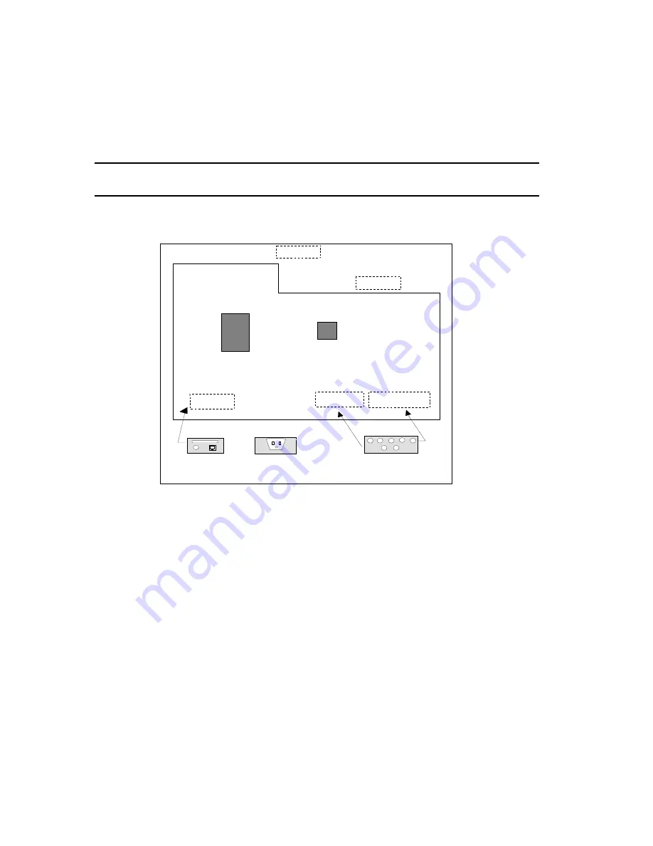
Figure 3-2 illustrates the relationship between PC boards
{
XE "Standalone:Board/connector
relationship"
}
attached to the bulkhead inside the cabinet and the connectors on the exterior
surface of the cabinet.
There is a LINE PRINTER/NETWORK connector on the bottom left side of the cabinet.
Only the LINE PRINTER connector is used in a standalone configuration.
tiger02 1
KEYBO AR D M O U S E
M O N IT O R
LIN E PR IN T ER
N E TW O R K
IN PU T POW ER
PR T C O N
N o B oard R eq uired for
M onitor (P ass T hrou gh)
KEM C O N
C AM E R A
C O N T R O LLER
BO AR D
SC AN N E R
C O N T R O LLER
M AIN BO AR D
Figure 3 – 2: Standalone Board/Connector Locations
Page 24
5000
i
Scanner Installation Guide
Содержание 5000i
Страница 1: ...Installation Guide For the 5000i Scanner NCS Pearson Publication Number 202 234 027...
Страница 2: ......
Страница 3: ...Installation Guide For the 5000i Scanner NCS Pearson Publication Number 202 234 027...
Страница 6: ...iv 5000i Scanner Installation Guide...
Страница 8: ...vi 5000i Scanner Installation Guide...
Страница 12: ...x 5000i Scanner Installation Guide...
Страница 17: ...Chapter 1 Scanner Overview Page 5...
Страница 31: ...Chapter 2 Scanner Installation Page 19...
Страница 38: ...Ensure that the SIMMs on the Catgut II board are fully seated Page 26 5000i Scanner Installation Guide...
Страница 47: ...Chapter 3 Computer and Peripherals Installation Page 35...
Страница 52: ...Page 40 5000i Scanner Installation Guide...


