background image


 Version 18.02.2022 

HW:CAM(V100)/(V47) 

RL4-MBMC 

P

a

g

e

6


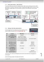
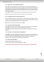
1.4.1.


Adjustment 

 power supply output (dip 1) 

 
If set to 

ON

, the video interfaces’ red wire 

will 12V (max 3A) with engaging the 

reverse gear and additionally 10 more seconds delay for the time of the front camera’s back

-

switching after the reverse gear has been disengaged. Furthermore, the 

red wire’s 

power 

supply for the front cam becomes active with manually front camera switching (short press 
of the external keypad). 
If set to 

OFF

, the video interfaces’ red wire will supply per12V ACC (max 3A).


Description of the power supply output: see chapter “Power supply output”.


1.4.2.


Enabling the interface’s video inputs (dip 2

-3) 


Only the enabled video inputs can be accessed by switching through the interface’s video 

sources. It is recommended to enable only the required inputs. Then the disabled inputs will 
be skipped while switching through the video interfaces inputs. 
 

Note:

 Dip 4 is out of function and has to be set to 

OFF

 
1.4.3.


Rear-view camera settings (dip 5) 


If set to 

OFF

, the interface switches to factory picture while the reverse gear is engaged to 

display factory rear-view camera or factory optical park system picture. 
If set to 

ON

, the interface switches to its rear-view camera input while the reverse gear is 

engaged. 

 
1.4.4.


Activation 

 front camera back-switching (dip 6) 


If set to 

ON

, the interface switches for 10 seconds from the rear-view camera to the front 

camera input after having disengaged the reverse gear. In addition, a manual switch-over to 
the front camera input is possible via keypad (short press) from any image mode. 
(Attend to correct adjustment of the power supply output (dip1)! 

 
1.4.5.


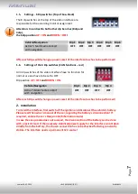
Monitor selection (Dip 8) 


Dip switch 8 determines the type of monitor. 
For the 10.25inch monitor, the dip switch position is 

OFF


After each Dip-switch-change a power-reset of the interface box has to be performed! 


Содержание RL4-MBMC

Страница 1: ...puts Product features Video inserter for factory infotainment systems 1 CVBS Input for rear view camera 1 CVBS Input for front camera 2 CVBS Video inputs for after market Video sources e g DVD Player...

Страница 2: ...tion 2 1 Place of installation and connection 2 2 Connection schema 2 3 Connection picture signal cable 2 4 Installation with connection to CAN bus or analogue without CAN bus 2 4 1 Connection 31pin P...

Страница 3: ...e offer free software updates for our interfaces To receive a free update the interface has to be sent in at own cost Wages for de and reinstallation and other expenditures involved with the software...

Страница 4: ...If 2 audio sources shall be connected to the infotainment an additional electronic is necessary to switch them Factory rear view camera Automatically switching back from inserted video to factory rea...

Страница 5: ...o interface Dip position UP OFF and DOWN ON The front camera will automatically be switched for 10 seconds after disengaging the reverse gear See the following chapters for detailed information Dip Fu...

Страница 6: ...e disabled inputs will be skipped while switching through the video interfaces inputs Note Dip 4 is out of function and has to be set to OFF 1 4 3 Rear view camera settings dip 5 If set to OFF the int...

Страница 7: ...for normal use and have to be set to OFF Dip position UP OFF and DOWN ON Vehicle Navigation Dip 1 Dip 2 Dip 3 Dip 4 Actros 5 Multimedia Cockpit with navigation OFF OFF OFF OFF After each Dip switch ch...

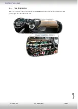
Страница 8: ...Version 18 02 2022 HW CAM V100 V47 RL4 MBMC Page 8 2 1 Place of installation The video interface has to be installed near the MBUX head unit which is located on the passenger side above the footwell...

Страница 9: ...Version 18 02 2022 HW CAM V100 V47 RL4 MBMC Page 9 2 2 Connection schema...

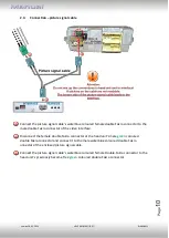
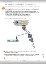
Страница 10: ...tor of the video interface Disconnect the female double Fakra connector at the head unit s male green coloured double Fakra connector and connect it to the male waterblue coloured double Fakra onnecto...

Страница 11: ...s also possible In this case via 12V switch inputs the interface is switched on see Connection 31pin PNP cable analogue without CAN bus or Connection 10pin power cable analogue without CAN Bus 2 4 1 C...

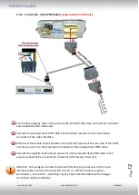
Страница 12: ...emale 31pin connector of the factory harness at the rear side of the head unit and connect it to the male 31pin connector of the enclosed 31pin PNP cable Connect the opposite female 31pin connector of...

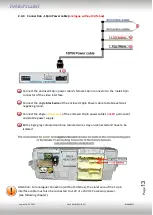
Страница 13: ...k wire of the enclosed 10pin Power cable to stabile vehicle s negative ground Connect the single yellow wire of the enclosed 10pin power cable to 12V permanent and stabile power supply Both single gre...

Страница 14: ...the 12pin interface cable to S contact terminal 86s e g glove compartment illumination Connection to ACC Accessory power not sufficient Note Only as long as the video interface is switched on via 12V...

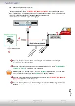
Страница 15: ...12pin power cable s female 12 pin connector to the male 12 pin connector of the video interface Connect the revers light power cable to the green switch input cable Reverse signal input 12V 24V of th...

Страница 16: ...nd additionally 10 seconds delay after reverse gear is disengaged Note In addition a manual switch over to the front camera input is possible via keypad short press from any image mode The power suppl...

Страница 17: ...y be used to power an external source and has a different assignment depending on the position of dip switch 1 of the black 8 dips Dip Function Dip 1 ON 12V max 3A when reverse gear is engaged incl 10...

Страница 18: ...ernal keypad Connect the female 4pin connector of the keypad to the male 4pin connector of the 12pin interface cable Note Even if switching through several video sources by the keypad mightn t be requ...

Страница 19: ...o changes in the production of the vehicle manufacturer there s always a possibility of incompatibility Connect the 12pin interface cable s female 12pin connector to the male 12pin connector of the vi...

Страница 20: ...he rear side of the video interface Press the MENU button to open the OSD settings menu or to switch to the next menu item Press UP and DOWN to change the selected value The buttons are placed inside...

Страница 21: ...press will switch to the next enabled input Inputs which are not enabled will be skipped Note The interface switches after releasing the switch after long pressure Short press of keypad only if DIP 1...

Страница 22: ...r order of LVDS cables is exactly connected according to manual Plugging into head unit does not work when the manual says to plug into monitor and vice versa Wrong monitor settings of video interface...

Страница 23: ...M button CAN bus interface does not support this function for vehicle Use external keypad or cut white wire of 6pin to 8pin cable and apply 12V impulses for AV switching Pressed too short For video so...

Отзывы: