© National Instruments Corporation
E-1
SCXI-1120 User Manual
Appendix E
SCXI-1120 Cabling
This appendix describes how to use and install the hardware accessories for the SCXI-1120:
•
SCXI-1340 cable assembly
•
SCXI-1341 Lab-NB, Lab-PC, and Lab-PC+ cable assembly
•
SCXI-1342 PC-LPM-16 cable assembly
•
SCXI-1344 Lab-LC cable assembly
•
SCXI-1180 feedthrough panel
•
SCXI-1302 50-pin terminal block
•
SCXI-1351 one-slot cable extender
•
SCXI-1350 multichassis adapter
•
SCXI-1343 screw terminal adapter
SCXI-1340 Cable Assembly
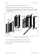
The SCXI-1340 cable assembly connects an MIO-16 board to an SCXI-1120 module. The
SCXI-1340 consists of a 50-conductor ribbon cable that has mounting bracket at one end and a
50-pin female connector at the other end. The female connector connects to the I/O connector of
the MIO-16 board. Attached to the mounting bracket is a 50-pin female mounting-bracket
connector that connects to the module rear signal connector. To extend the signals of the
MIO-16 board to an SCXI-1180 feedthrough panel or an SCXI-1181 breadboard module, you
can use the male breakout connector that is near the mounting bracket on the ribbon cable. All
50 pins from the MIO-16 board go straight through to the rear signal connector. You can use a
standard 50-pin ribbon cable instead of the SCXI-1340 cable assembly. The SCXI-1340 has the
following advantages over the ribbon cable:
•
The SCXI-1340 has strain relief so that you cannot accidentally disconnect the cable.
•
The SCXI-1340 includes a mounting bracket that mounts to the chassis so that you can
remove and reinsert the module without explicitly removing the cable from the back of the
chassis. This is especially useful when the SCXI chassis is rack mounted, making rear access
difficult.
•
The SCXI-1340 has an extra male breakout connector for use with the SCXI-1180
feedthrough panel or additional modules or breadboards that need a direct connection to the
MIO-16 board.
•
The SCXI-1340 rear panel gives the module and the chassis both mechanical and electrical
shielding.


