Configuration and Installation
Chapter 2
SCXI-1120 User Manual
2-20
© National Instruments Corporation
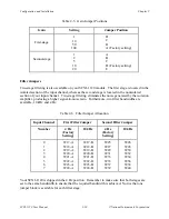
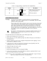
Table 2-8. Jumper Settings on the SCXI-1328 Terminal Block
Jumper
Position
Description
W1
DTEMP
MTEMP
•
•
•
•
MTS mode selected; factory
setting; parking position
W1
•
•
•
•
DTEMP
MTEMP
DTS mode selected
Terminal Block Signal Connection
Warnings:
The chassis GND terminals on your terminal block are for grounding high
impedance sources such as a floating source (1 mA maximum). Do not use these
terminals as safety earth grounds.
If high voltages (
≥
42 Vrms) are present, you must connect the safety earth ground
to the strain-relief tab. This complies with UL 1244 and protects against electric
shock when the terminal block is not connected to the chassis. To connect the
safety earth ground to the strain-relief tab, run an earth ground wire in the cable
from the signal source to the terminal block. National Instruments is not liable for
any damages or injuries resulting from inadequate safety earth ground
connections.
!
Shock Hazard: This unit should only be opened by qualified personnel aware of
the dangers involved. Disconnect all power before removing cover. Always
install grounding screw.
To connect the signal to the terminal block, use the following procedure:
1. Remove the grounding screw of the top cover.
2. Snap out the top cover of the shield by placing a screwdriver in the groove at the bottom of
the terminal block.
3. Slide the signal wires, one at a time, through the front panel strain-relief opening. You can
add insulation or padding if necessary.
4. Connect the wires to the screw terminals by wrapping the wires around the screws and
tightening the screws without letting the wires slip out.
5. Tighten the larger strain-relief screws.
6. Snap the top cover back in place.
7. Reinsert the grounding screw to ensure proper shielding.
8. Connect the terminal block to the SCXI-1120 front connector as explained in the Terminal
Block Installation section later in this chapter.
Figure 2-9 shows a parts locator diagram for the SCXI-1320 terminal block. Figure 2-10 shows
a parts locator diagram for the SCXI-1328 terminal block.


