


Chapter 2
Configuration and Installation
© National Instruments Corporation
2-9
SCXI-1120 User Manual
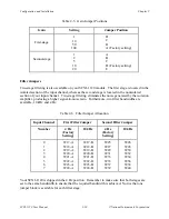
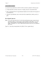
Table 2-3. Jumper W41 Settings
Jumper
Description
Configuration
W41
Temperature sensor
accessed in MTS mode
(Factory setting)
•
•
•
3 2 1
W41
Temperature sensor
accessed in DTS mode,
data acquisition board
configured for NRSE or
RSE
•
•
•
3 2 1
Gain Jumpers
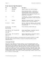
Each input channel has two gain stages. The first gain stage provides gains of 1, 10, 50, and 100,
and the second stage provides gains of 1, 2, 5, 10, and 20. Tables 2-4 and 2-5 show how to set
up the gain for each channel.
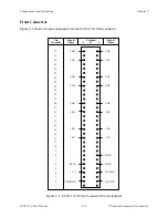
Table 2-4. Gain Jumper Allocation
Input Channel Number
First Gain Jumper
Second Gain Jumper
0
W1
W9
1
W2
W10
2
W3
W11
3
W4
W12
4
W5
W13
5
W6
W14
6
W7
W15
7
W8
W16
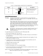
The board is shipped with the first-stage gain set to 100 (position A), and a second-stage gain set
to 10 (position D). To change the gain of your module, move the appropriate jumper on your
module to the position indicated in Tables 2-3 and 2-4. Refer to Figure 2-1, SCXI-1120 General
Parts Locator Diagram, and Figure 2-2, Detailed Parts Locator Diagram, for jumper locations
on your module.
To determine the overall gain of a given channel use the following formula:
Overall gain = First-stage gain x second-stage gain.


