Installation and Configuration of the GPIB-SCSI-A
Chapter 2
GPIB-SCSI-A User Manual
2-2
© National Instruments Corp.
Step 2. Configure the Operating Characteristics
The GPIB-SCSI-A is shipped from the factory configured to operate in S
mode. Optional parity checking on the SCSI port is disabled. The SCSI ID
that the GPIB-SCSI-A responds to is set at 5, and the primary GPIB address
is set at 0. Additionally, the GPIB-SCSI-A is shipped from the factory with
a SCSI terminating resistor pack installed. Depending on your system, you
may want to remove it.
Configuration Switch Settings for SW1
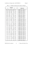
The DIP switch at location SW1 on the rear panel is used to configure the
power-on primary GPIB address and SCSI ID of the GPIB-SCSI-A. The
DIP switch has eight configuration switches.
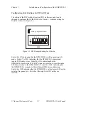
The factory default setting is shown in Figure 2-1. In this figure, the black
side of the switch is the side of the switch you press down.
SW1
1 2 3 4 5 6 7 8
O
N
Key
= side you press down
Figure 2-1.
SW1 Default Mode Switch Settings
Figure 2-1 shows the factory default setting of the GPIB-SCSI-A for switch
SW1. Switches 1 through 3 are ON, OFF, ON, respectively, to indicate that
the SCSI ID of the GPIB-SCSI-A is 5. Switches 4 through 8 are OFF to
indicate that the primary GPIB address of the GPIB-SCSI-A is 0.
Содержание GPIB-SCSI-A
Страница 20: ......
Страница 27: ......
Страница 355: ...Appendix C Operation of the GPIB National Instruments Corp C 7 GPIB SCSI A User Manual Figure C 2 Linear Configuration ...
Страница 356: ...Operation of the GPIB Appendix C GPIB SCSI A User Manual C 8 National Instruments Corp Figure C 3 Star Configuration ...


