Contents
GPIB-SCSI-A User Manual
xiv
© National Instruments Corp.
Figures
Figure 1-1. GPIB-SCSI-A........................................................................1-1
Figure 1-2. The GPIB-SCSI-A Rear Panel ..............................................1-8
Figure 1-3. The SCSI Connector and Signal Designations......................1-9
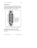
Figure 1-4. The GPIB Connector and Signal Assignments ..................... 1-10
Figure 1-5. SCSI Computer Controlling GPIB Devices ..........................1-11
Figure 1-6. A SCSI Bus Connected to a GPIB Controller....................... 1-12
Figure 2-1. SW1 Default Mode Switch Settings ..................................... 2-2
Figure 2-2. SW2 Default Switch Settings ................................................2-5
Figure 2-3. SW2 Sample Setting for G Mode..........................................2-7
Figure 2-4. GPIB-SCSI-A Physically Located at End of SCSI Bus ........2-9
Figure 2-5. GPIB-SCSI-A Not Physically Located at End of
SCSI Bus............................................................................... 2-10
Figure 4-1. Command Descriptor Block Example................................... 4-2
Figure 6-1. Serial Poll Status Byte........................................................... 6-24
Figure 7-1. Valid Bits of mask................................................................. 7-13
Figure C-1. The GPIB Connector and Signal Assignments..................... C-6
Figure C-2. Linear Configuration ............................................................C-7
Figure C-3. Star Configuration ................................................................C-8
Figure D-1. Standard 50-Pin SCSI Connector......................................... D-7
Figure D-2. Daisy-Chain Configuration of the SCSI Bus ....................... D-11
Tables
Table 1-1. Electrical Characteristics ........................................................1-4
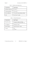
Table 1-2. Environmental Characteristics................................................1-5
Table 1-3. Physical Characteristics ..........................................................1-5
Table 1-4. Maximum Transfer Rates ....................................................... 1-6
Table 1-5. LED Descriptions ................................................................... 1-7
Table 2-1. Configuration Parameters for Switches 1 through 3............... 2-3
Table 2-2. Configuration Parameters for Switches 4 through 8............... 2-4
Table 2-3. Possible Configurations for SW2 in S Mode ......................... 2-6
Table 2-4. Possible Configurations for SW2 in G Mode......................... 2-8
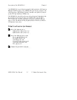
Содержание GPIB-SCSI-A
Страница 20: ......
Страница 27: ......
Страница 355: ...Appendix C Operation of the GPIB National Instruments Corp C 7 GPIB SCSI A User Manual Figure C 2 Linear Configuration ...
Страница 356: ...Operation of the GPIB Appendix C GPIB SCSI A User Manual C 8 National Instruments Corp Figure C 3 Star Configuration ...


