G Mode Functions
Chapter 7
GPIB-SCSI-A User Manual
7-114
© National Instruments Corp.
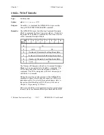
write
(continued)
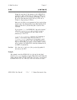
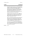
During the execution of this command, if the GPIB-SCSI-A
encounters a phase which it does not expect, an EPHS error
indication results. For a list of the expected phases, refer to
the section titled Handling of SCSI Phases in G Mode in
Chapter 6, Programming in G Mode.
Refer to your SCSI device documentation for expected values
in each byte of the Command Descriptor Block and the SCSI
phases that the device creates during the execution of this
command.
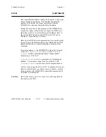
If you enter
write?
, the GPIB-SCSI-A places the last used
values for
logical
block
address
and
transfer
length
into the Command and Status Channel buffer
followed by a <CR><LF>.
logical
block
address
represents a 21-bit unsigned
number. Correct values range from 0 to 2,097,152.
transfer
length
represents an 8-bit unsigned number.
Correct values range from 0 to 255. If numbers that are too
large are entered, there is a syntax error in a number, or there
are no numbers, the GPIB-SCSI-A aborts the command with
an EARG error indication.
See Also:
dtin, dtout, rdext, read, wrext, blksz, pad, and Appendix D,
Operation of the SCSI.
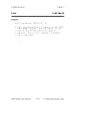
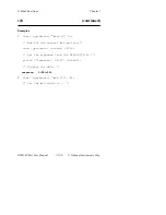
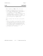
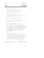
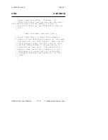
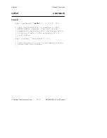
Example:
This example causes the GPIB-SCSI-A to write ten blocks of data
(stored in
databuf
) beginning at Logical Block Address 100 from the
Target with a SCSI ID of 4 and a blocksize of 512 bytes. The byte that
the GPIB-SCSI-A uses as a filler byte will be the line feed character.
Содержание GPIB-SCSI-A
Страница 20: ......
Страница 27: ......
Страница 355: ...Appendix C Operation of the GPIB National Instruments Corp C 7 GPIB SCSI A User Manual Figure C 2 Linear Configuration ...
Страница 356: ...Operation of the GPIB Appendix C GPIB SCSI A User Manual C 8 National Instruments Corp Figure C 3 Star Configuration ...


