Chapter 2
Installation and Configuration of the GPIB-SCSI-A
© National Instruments Corp.
2-5
GPIB-SCSI-A User Manual
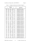
Configuration Switch Settings for SW2 in S Mode
The DIP switch at location SW2 on the rear panel is used to configure the
mode of operation for the GPIB-SCSI-A. The DIP switch has eight
configuration switches.
Figure 2-2 shows the factory default switch settings for SW2.
SW2
1 2 3 4 5 6 7 8
O
N
Key
= side you press down
Figure 2-2. SW2 Default Switch Settings
Switch 8 is OFF, indicating that the GPIB-SCSI-A will be operating in S
mode. Switch 7 is ON, indicating that the GPIB-SCSI-A will neither notice
nor report SCSI parity errors. Switch 6 is ON, indicating that the
GPIB-SCSI-A will buffer data during data transfer commands. Switch 5 is
OFF, indicating that the GPIB-SCSI-A will complete all data requests to the
exact count specified. Switches 4 is ON, indicating that double buffering
will be used. Switches 1 through 3 are OFF because they are reserved.
Содержание GPIB-SCSI-A
Страница 20: ......
Страница 27: ......
Страница 355: ...Appendix C Operation of the GPIB National Instruments Corp C 7 GPIB SCSI A User Manual Figure C 2 Linear Configuration ...
Страница 356: ...Operation of the GPIB Appendix C GPIB SCSI A User Manual C 8 National Instruments Corp Figure C 3 Star Configuration ...


