Theory of Operation
Chapter 3
SCXI-1100 User Manual
3-10
© National Instruments Corporation
Fr
ont Connector
MUX0
and Input Protection
MUX1
and Input Protection
MUX2
and Input Protection
MUX3
and Input Protection
MUX4
and Input Protection
MUX5
and Input Protection
MUX6
and Input Protection
MUX7
and Input Protection
MUXCOUNTER
and
Channel Select
Calibration
and
Auto-Zero
Hardware
PGIA
+
–
Input Channel
Select
Calibration or
Input Selection
Auto-Zero or
Auto-Calibration
Selection
From AB2
±
Gain Select
Timing Signals
To Output Multiplexer
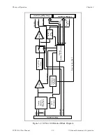
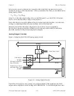
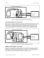
Figure 3-6. Analog Input and Timing Block Diagram
The analog input and timing circuitry consists of an input multiplexer, channel select hardware, a
software-programmable gain instrumentation amplifier, and calibration hardware.
The input multiplexer consists of eight CMOS analog input multiplexers and has 32 differential
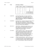
analog input channels. Input channels and multiplexers correspond as shown in Table 3-2.


