Register Descriptions
Chapter 4
SCXI-1100 User Manual
4-4
© National Instruments Corporation
Bit
Name
Description (continued)
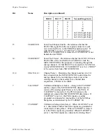
Bit 20
Bit 19
Bit 18
Second-Stage Gain
0
0
0
1
0
0
1
2
0
1
0
5
0
1
1
10
1
0
0
20
1
0
1
not valid (open loop)
1
1
0
not valid (open loop)
1
1
1
not valid (open loop)
15
CLKOUTEN
Scan Clock Output Enable – Determines whether the
SCANCLK signal from the rear signal connector is sent
out, in inverted form, to the TRIG0 backplane signal. If
CLKOUTEN is set to 1, SCANCLK* is transmitted on
TRIG0. If CLKOUTEN is cleared to 0, SCANCLK* is not
transmitted on TRIG0.
14
CLKSELECT
Scan Clock Select – Determines whether the SCXI-1100 uses
SCANCLK or the inverted form of TRIG0 to clock the
MUXCOUNTER for the purposes of scanning through the
analog channels. If CLKSELECT is cleared to 0, SCANCLK
clocks MUXCOUNTER. If CLKSELECT is set to 1, TRIG0*
is the source that clocks MUXCOUNTER.
12-8
CHAN<4..0>
Channel Select – Determine the channel number (0 to 31)
that is loaded into the MUXCOUNTER to determine the
analog channel to be read during a single read, or the
starting channel on the module for a scanned data
acquisition. CHAN4 is the MSB.
7
CAL/ENM*
Calibration/Multiplexer Select – Along with CV/ZERO*
and the output of the MUXCOUNTER, determines the
source of the analog signal that is sent to the PGIA. If
CAL/ENM* is cleared to 0, the PGIA inputs are the
multiplexer outputs that MUXCOUNTER determines. If
CAL/ENM* is set to 1, the PGIA inputs are either
grounded or connected to Analog Bus 2 of the SCXIbus
backplane, as determined by the CV/ZERO* bit.
6
CV/ZERO*
Calibration Voltage/Zero Select – When CAL/ENM* is set
to 1, determines whether the PGIA inputs are grounded or
connected to Analog Bus 2. When CV/ZERO* is cleared
to 0, the PGIA inputs are grounded. When CV/ZERO* is
set to 1, the PGIA inputs are connected to Analog Bus 2.


