Machine Operation
www.nationalequipment.com
Phone: 763-315-5300
16
CYLINDER LIFT (FIGURE T)
The cylinder lift lever raises and lowers the cylinder and cutting head. After setting slide
plate to proper height, use the cylinder lift lever to set blade to proper cutting angle. Pull
back
on the cylinder lift lever to raise the cutting head. Push the cylinder lift lever for-
ward
to lower the cutting head. Continuing to push the cylinder lift lever forward and
it will adjust the angle of the cutting head. This will also jack up the front of the machine
(Figure U). This will need to be done when doing maintenance on the machine (ie: wheel
changing, front caster maintenance etc). When doing machine maintenance, besides
raising the cutting head angle, place blocks under the machine (Figure V). Never use the
cutting head only.
OPERATIONAL TIPS
CASTER
Keep clean and free of debris, make sure it can move freely. Clean as needed. Inspect
before each use. Grease once a month.
Moving a “weighted” machine only on the front caster and not on the cutting head or the
Front Wheel Assembly can seem to make the machine turn sluggish. It might turn hard to
the right or the left. This is normal.
FOOT PEG
Keep feet resting and secured on foot pegs when operating machine. Foot pegs are
adjustable. Make sure securing nut is securely tightened
SEAT
Always be properly seated before operating machine. Machine will not run if the operator
is not properly seated
DISARM MACHINE
Remove blade or drop cutting head to the
fl
oor when machine is not in use.
LEAKAGE
Keep
fi
ttings and hoses tight. If a leak is noticeable, retighten
fi
tting. If leakage persists,
remove the connection and inspect.
ANGLE OF THE HEAD IS SET STEEP
When raising the front of the machine to a steep angle, the bottom of the slide plate
should be raised so it is higher or even with the bottom of the guide channels, 15 to 18
cm (6” to 7”) off the
fl
oor. This will allow for a steep blade angle without tipping the ma-
chine too far back and is usually used for re-scraping. The most common mode for take
up has the slide plate approximately 2.5 cm (1”) from the
fl
oor.
FIG. T
FIG. U
FIG. V
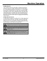
WARNING:
DO NOT ALTER A SWITCH OR LEVER. DO NOT DEFEAT A
SAFETY DEVICE.
WARNING:
DISARM MACHINE BY REMOVING THE CUTTING HEAD OR
DROPPING THE CUTTING HEAD TO THE FLOOR WHEN THE MACHINE IS NOT
IN USE.
Содержание 5700-aus
Страница 1: ...Read Manual Before Operating Machine ALL DAY BATTERY RIDE ON SCRAPER INSTRUCTION MANUAL Rev B 401810...
Страница 2: ......
Страница 44: ...Parts List and Diagrams Fax 763 535 8255 info nationalequipment com 44 5700 BATTERY WIRING...
Страница 46: ...Parts List and Diagrams Fax 763 535 8255 info nationalequipment com 46 5700 MACHINE WIRING...


