W415-1066 / A / 03.06.12
24
NOTE
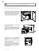
The connector is not symmetric and can only fit into the knock out in one orientation.
Push connector down until it “locks” into bulk head.
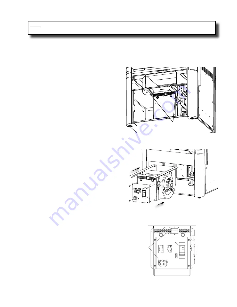
The second part of the installation requires removing
the blower assembly to allow easy installation of the
electric furnace control board to the main electric con-
trol board. Start by removing the hex head securing
screws that fasten the blower assembly guide rails to
the bottom of the blower division bulk head.
remove ScreWS
disconnect the (3) electrical quick connects from the
main electrical control panel.
gently slide the blower assembly out the front of the
furnace. locate and secure the electric furnace con-
trol board to the main electrical control board using
four (4) hex head screws supplied with the hmfk-
ef10 kit.
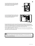
Take the (4) wires (f, f, c, 1) from the electric furnace
control board and connect them to the correspond-
ing terminals (f, f, c, 1) on the main electric control
board.
connect the 240v supply to the circuit breaker on the
electric furnace control board.
Slide the blower assembly back into the furnace and
re-attach the guide rails to the blower division bulk
head with the hex head screws. reconnect the (3)
wire harnesses that were disconnected to pull the
blower assembly out.
S4 S3 S2 S1 N F F C 1
7 8 9 10 11 G
GND.
F F C 1
L1 L2
TERMINALS
CIRCUIT BREAKER
Содержание HMF100
Страница 9: ...W415 1066 A 03 06 12 9 ...
Страница 43: ...W415 1066 A 03 06 12 43 11 0 service history 43 1 ...
Страница 44: ...W415 1066 A 03 06 12 44 44 1 12 0 notes ...


